An EO/IR gimbal is not simply a camera mounted under an aircraft. It is a tightly integrated sensing system in which optical payloads, inertial sensing, stabilization control, range measurement, data processing, mechanical structure, and aircraft interfaces must work together. A mismatch in any one of these areas can reduce image usability, pointing stability, detection range, platform endurance, or operator confidence.
This guide is written for UAV manufacturers, system integrators, engineering teams, and procurement specialists evaluating airborne intelligence, surveillance, and reconnaissance payloads. It focuses on lawful observation, inspection, mapping, search-and-rescue, infrastructure monitoring, border awareness, and other non-offensive sensing applications. It explains the questions that should be resolved before a gimbal is selected, how visible and infrared channels complement each other, where laser ranging can add value, and how to verify that the finished payload performs on the actual platform rather than only on a laboratory bench.
SentiAcu, a sensing technology brand associated with NeoFlux Limited, develops LiDAR and intelligent perception solutions for air, land, and sea applications. The engineering principles below are therefore organized around real integration decisions: target distance, field of view, vibration, update rate, interface, environmental conditions, size, weight, power, and the quality of information delivered to the operator or host computer.
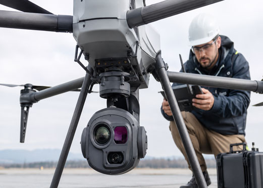
An EO/IR gimbal system is a stabilized, steerable payload that combines electro-optical and infrared sensors with motion control, inertial measurement, processing, and communication interfaces to maintain a usable line of sight from a moving platform.
“EO” normally refers to visible-light or near-visible imaging, while “IR” refers to infrared imaging that detects thermal radiation. The two channels provide different information. A daylight camera can deliver fine texture, color, readable markings, and strong identification detail under suitable illumination. A thermal imager can show temperature contrast at night or when visible contrast is weak. A well-designed system can present either channel independently, fuse or register them, and keep both aligned to a common pointing direction.
The gimbal itself provides controlled movement around two or more axes. A common configuration offers azimuth and elevation control, but the complete system also needs a reference for aircraft motion. Inertial sensors measure angular movement, control electronics command motors, encoders report position, and software closes the loop. The result should be a stable image and a predictable pointing direction even when the UAV is turning, vibrating, climbing, or encountering wind disturbances.
For engineering purposes, the EO/IR payload should be treated as a system of systems. The camera specification alone cannot predict mission performance. A high-resolution sensor can still produce poor results if the lens is unsuitable, the gimbal structure resonates, the stabilization bandwidth is too low, the boresight changes with temperature, the video is excessively compressed, or the host platform introduces electrical noise.
Mission-first EO/IR gimbal selection means defining the observation task, required evidence, operating environment, and platform limits before choosing individual sensors or optics.
The first question is not “How many megapixels does the camera have?” It is “What decision must the system support?” An inspection team may need to identify corrosion, cable damage, or thermal anomalies. A search-and-rescue operator may need to detect a person-sized heat source over complex terrain and then maintain visual contact. A mapping team may need accurate georeferenced imagery rather than continuous operator-controlled video. A perimeter awareness application may prioritize persistent coverage, low-light performance, and reliable target handoff.
Translate the mission into measurable requirements. Useful inputs include minimum and maximum slant range, expected target size, required detection or identification detail, day/night usage, atmospheric visibility, platform altitude, aircraft speed, allowed payload mass, available electrical power, video latency, communication bandwidth, and whether the host system needs geolocation or only imagery. These inputs prevent a common procurement error: buying a technically impressive payload that cannot deliver the required result on the intended aircraft.
Range should be linked to target detail, not treated as a single marketing number. A camera may detect that an object exists at a long distance while being unable to identify what it is. Likewise, a thermal channel may reveal a temperature anomaly but not provide enough spatial detail to classify equipment. Engineering teams should define separate detection, recognition, and identification objectives, then validate them under representative contrast, weather, and motion conditions.
Mission definition also clarifies whether a gimbal sensor needs continuous manual control, automated tracking, preset pointing, map-based cueing, or integration with other sensors. These modes require different software, control interfaces, timing accuracy, and operator workflows. A payload intended for occasional inspection can tolerate different constraints from a system expected to maintain a stable line of sight for extended periods.
The sensor payload is the collection of imaging, ranging, inertial, processing, and environmental components mounted within the stabilized gimbal and aligned to a common reference.
The visible channel normally combines an image sensor, lens, focus mechanism, exposure control, image processor, and video encoder. Key specifications include sensor format, pixel pitch, effective resolution, focal length range, aperture, optical zoom, focus speed, low-light sensitivity, dynamic range, rolling or global shutter behavior, and compression format. Resolution should always be evaluated with the optics and stabilization performance; more pixels do not compensate for blur, haze, or insufficient focal length.
Wide field of view supports search and situational awareness, while narrow field of view supports detail at distance. A zoom lens allows both, but zoom ratio alone is incomplete. Teams should compare actual horizontal and vertical fields of view at the wide and narrow ends, focus behavior during zoom, optical transmission, image quality across the frame, and whether stabilization remains effective at maximum focal length. Narrow fields of view magnify both target detail and pointing error.
Infrared payloads may use different spectral bands and detector technologies. Selection depends on target temperature contrast, atmospheric transmission, operating temperature, required resolution, cooldown requirements, size, power, cost, and export or regulatory considerations. The relevant procurement question is not simply whether the payload has thermal imaging, but whether the detector, lens, calibration, and image processing provide useful contrast for the mission environment.
Thermal non-uniformity correction, bad-pixel replacement, automatic gain control, image polarity, and digital enhancement can materially affect usability. Operators should be able to understand whether a bright or dark region represents real thermal contrast or an image-processing artifact. If EO and IR imagery are overlaid or switched rapidly, boresight alignment should be measured over zoom, temperature, and gimbal angle.
An inertial measurement unit measures angular rates and acceleration, while encoders measure gimbal-axis positions. Some systems also use magnetometers, GNSS time, aircraft attitude data, or external navigation information. The quality and timing of these signals influence stabilization and geolocation. A small timestamp mismatch between video, gimbal angle, and aircraft attitude can become a large location error at long slant range.
Processing may include image enhancement, electronic stabilization, target tracking, video encoding, metadata generation, sensor fusion, and communication management. Processing architecture affects latency and thermal load. Teams should distinguish between algorithm demonstration under ideal clips and sustained performance on the intended processor, frame rate, target type, and environment. Any automated tracking function should be tested for loss, reacquisition, clutter, crossing targets, rapid scale changes, and operator override.
Gimbal stabilization is the closed-loop process of measuring platform motion and commanding the payload axes to keep the optical line of sight steady relative to a selected reference.
Image stabilization is often described with a single angular value, but system behavior is more complex. The result depends on sensor noise, control-loop bandwidth, motor torque, structural stiffness, encoder resolution, mass balance, bearing friction, cable forces, vibration isolation, and the frequency content of aircraft disturbance. A specification measured on a rigid bench may not represent performance on a UAV with propeller vibration, flexible landing gear, turbulent airflow, or a resonant mounting plate.
Angular error converts into linear displacement at the target. As a simple illustration, an angular error of 1 milliradian corresponds to approximately 1 meter of line-of-sight displacement at 1 kilometer. This relationship is small-angle geometry, not a prediction of any specific SentiAcu product. It demonstrates why a payload that looks stable at wide field of view can appear unstable at high zoom or long range.
Stabilization should be assessed in both steady-state and dynamic conditions. Steady-state tests evaluate drift and jitter when the platform is relatively calm. Dynamic tests introduce sinusoidal motion, step commands, turns, accelerations, and representative vibration. Useful measurements include residual line-of-sight jitter, settling time, overshoot, tracking error, image smear, and the ability to maintain lock through gimbal-axis transitions.
Mechanical integration is equally important. The payload should be mounted to a structure with known stiffness and natural frequencies. Fasteners, dampers, cables, and connectors should not create asymmetric loads. The center of mass should remain within the gimbal design envelope, especially if a customer changes a lens or adds a sensor. A vibration isolator must be selected for the actual mass and disturbance spectrum; an isolator that is too soft can amplify low-frequency motion, while one that is too stiff may pass high-frequency vibration directly to the optics.
A laser rangefinder measures the distance to a target by transmitting optical energy and calculating the return time, phase, or another measurable property of the reflected signal.
Time-of-flight ranging is based on the travel time of light. The exact speed of light in vacuum is 299,792,458 meters per second, as defined in the International System of Units. In practical atmospheric sensing, the system must account for the round trip, detector response, timing electronics, signal processing, target reflectivity, beam divergence, atmospheric attenuation, and background light. A nominal maximum range is therefore meaningful only when the target and test conditions are stated.
Adding a laser rangefinder can support distance measurement, focus or tracking assistance, altitude awareness, and more accurate line-of-sight interpretation. It does not automatically create precise target coordinates. Geolocation also depends on aircraft position, aircraft attitude, gimbal angles, boresight calibration, timing synchronization, terrain data, and error propagation across the entire chain.
Important rangefinder parameters include wavelength, minimum and maximum range, accuracy, update rate, beam divergence, receiver field of view, false-alarm behavior, multi-return capability, eye-safety classification where applicable, operating temperature, mass, dimensions, power, and communication interface. Teams should ask whether the published range applies to a high-reflectivity cooperative target, a specified diffuse target, or an unspecified ideal condition.
Alignment is a frequent source of integration error. The laser transmitter axis, receiver field, visible camera axis, thermal camera axis, and gimbal reference must be calibrated. The alignment can shift with temperature, shock, zoom position, or mechanical service. A robust system includes a repeatable boresight process and a way to verify alignment during production and maintenance.
Range quality should be communicated to the operator. Instead of displaying an unqualified number, the interface may need validity, confidence, last-update time, or an out-of-range indication. This prevents stale or low-confidence measurements from being treated as certain. Where multiple sensors are used, ranging should be time-aligned with the video frame and gimbal attitude that produced the observation.
A payload configuration is a selected combination of imaging and ranging channels designed to meet a particular mission while remaining within the platform’s size, weight, power, cost, and data limits.
| Configuration | Primary strengths | Typical limitations | Best-fit tasks | Integration emphasis |
|---|---|---|---|---|
| Visible EO only | Fine visual detail, color, lower payload complexity | Dependent on illumination and visual contrast | Daylight inspection, mapping support, documentation | Optics, zoom stability, exposure, bandwidth |
| EO + uncooled IR | Day/night observation and thermal contrast without a cooled detector | Thermal detail and long-range performance depend strongly on detector and optics | Search and rescue, infrastructure inspection, perimeter awareness | Dual-channel alignment, thermal calibration, video switching |
| EO + high-performance IR | Improved long-range thermal sensitivity and detail where appropriately specified | Higher cost, power, thermal management, and possible cooldown needs | Persistent observation and demanding night operations | Power, heat rejection, environmental control, export compliance |
| EO/IR + single-point rangefinder | Adds direct distance measurement with relatively compact data output | Measures along one line of sight; performance depends on target return and alignment | Inspection, range-aware tracking, platform height or target distance measurement | Boresight, timing, beam divergence, validity reporting |
| EO/IR + scanning or array LiDAR | Adds spatial depth or point-cloud information | Greater data, processing, mass, power, and calibration demands | Terrain mapping, obstacle awareness, 3D scene understanding | Data pipeline, coordinate frames, synchronization, compute capacity |
| EO/IR + RF cueing | Combines optical confirmation with wider-area or complementary detection | Requires multi-sensor fusion and careful time/coordinate alignment | Wide-area monitoring and sensor-to-sensor handoff | Track association, latency, confidence, operator workflow |
The comparison illustrates why “more sensors” is not automatically better. Each added channel increases calibration, power, heat, data, software, and maintenance requirements. The best architecture is the smallest configuration that provides the information needed for the mission with adequate reliability and growth margin.
SWaP-C is the combined engineering constraint of size, weight, power, and cost, which determines whether a sensor payload can be carried, powered, cooled, controlled, and economically supported by the intended UAV.
Weight affects aircraft endurance, center of gravity, structural loads, and vibration behavior. The quoted payload mass should include mounting hardware, cables, isolation hardware, interface boxes, and any external processor. A small difference on the product datasheet can become significant after integration components are included. The aircraft team should model worst-case mass, not only the bare gimbal.
Power should be specified for startup, nominal operation, peak motor activity, heaters, cooling, and optional sensors. Voltage range, transient behavior, inrush current, conducted emissions, and grounding are important. A payload that operates on a laboratory supply may reset or introduce noise when connected to an aircraft power bus. The integration plan should include power conditioning and electromagnetic compatibility testing.
Thermal management is often overlooked. Electronics, processors, motors, and infrared components generate heat, while an airborne enclosure may experience cold ambient temperatures and limited convective cooling in certain conditions. Designers should evaluate internal temperatures at high and low ambient conditions, solar loading, hover, forward flight, and stationary ground operation. Thermal drift can affect alignment and measurement accuracy even before a component reaches its absolute temperature limit.
Interfaces should be defined at physical, electrical, protocol, timing, and data-model levels. Typical needs include power, video, command and control, telemetry, metadata, synchronization, diagnostics, and firmware update. Ethernet alone does not guarantee interoperability. The parties must agree on packet formats, coordinate frames, units, time base, error codes, connection recovery, cybersecurity controls, and ownership of integration software.
Where optical and radio-frequency sensing are combined, the lidar and radar architecture should define which sensor detects, which confirms, how tracks are associated, and what happens when measurements disagree. Fusion should preserve uncertainty rather than forcing incompatible observations into a falsely precise answer.
An integration workflow is a controlled sequence that converts mission requirements into a verified airborne payload through interface definition, mechanical and electrical design, calibration, software integration, and representative testing.
Write the mission requirements document. Define target classes, ranges, illumination, weather assumptions, platform altitude and speed, required output, operator workflow, regulatory constraints, and acceptance criteria.
Create an error budget. Allocate allowable error across camera resolution, stabilization, aircraft navigation, gimbal angle, boresight, timing, ranging, and terrain data. This reveals whether the requested system-level performance is physically consistent.
Select the minimum viable sensor stack. Choose EO, IR, ranging, and other channels based on the information required, not on feature count. Record which requirement each sensor satisfies.
Freeze coordinate frames and interfaces. Document aircraft body, gimbal, sensor, and navigation frames. Define axes, angle signs, units, timestamps, message rates, cable pinouts, protocols, and failure behavior.
Model mechanical and thermal behavior. Check center of gravity, structural stiffness, mounting loads, isolation, cable routing, heat generation, airflow, and service access.
Perform bench integration. Verify power, startup, commands, video, telemetry, focus, zoom, range output, metadata, fault reporting, and firmware update without flight variables.
Calibrate boresight and timing. Align sensor axes, verify synchronization, measure offsets across temperature and zoom, and store configuration in a controlled way.
Run motion and vibration tests. Use representative angular motion and vibration spectra. Measure residual jitter, settling, video quality, tracking continuity, and connector stability.
Conduct restrained platform tests. Operate on the actual aircraft while safely restrained or in a controlled ground configuration. Look for electromagnetic interference, power transients, GNSS effects, thermal issues, and vibration modes.
Execute progressive flight tests. Begin with wide margins and simple maneuvers, then add zoom, tracking, ranging, night operation, temperature, altitude, and complex backgrounds. Record synchronized raw data for analysis.
Verify maintainability. Define calibration checks, firmware control, cleaning, connector inspection, replacement procedures, log retrieval, and acceptance tests after service.
A disciplined workflow reduces late redesign. It also creates evidence that procurement teams can use to compare vendors on more than brochure specifications.
Acceptance testing is a documented set of repeatable measurements used to confirm that the delivered gimbal meets agreed image, pointing, ranging, environmental, interface, and reliability requirements.
Begin with traceable configuration control. Record hardware revision, optics, firmware, calibration files, aircraft software, environmental conditions, test range, target, and operator settings. Without this information, two apparently different results may simply reflect different configurations.
Image tests should cover resolution, focus, zoom repeatability, low-light performance, dynamic range, thermal non-uniformity, dead pixels, frame rate, compression, and latency. Use targets appropriate to the required detail and avoid relying only on visually pleasing footage. A sharpened image can look better while containing no additional real information.
Stabilization tests should include static jitter, slow drift, commanded motion, step response, sinusoidal disturbance, aircraft turns, and vibration. Report the measurement method and frequency band. If the requirement is linked to target detail at range, convert angular results into expected image displacement and compare with pixel scale at relevant focal lengths.
Range tests should use targets with documented size, reflectivity or material, angle, distance, background, visibility, and illumination. Test minimum range, required operational ranges, repeatability, invalid-return behavior, and update rate. Do not extrapolate a result on a large reflective board to a small low-reflectivity target.
Environmental testing should reflect the product’s stated operating envelope and the customer’s real conditions. Temperature cycling, vibration, shock, humidity, dust, water exposure, electromagnetic compatibility, and storage may be relevant. The required standards depend on industry, jurisdiction, platform, and contract; they should be agreed before design freeze, not after manufacturing.
A procurement mistake is a requirement, comparison, or contracting decision that causes the selected payload to underperform, cost more to integrate, or become difficult to verify and maintain.
Comparing only camera resolution. Optics, pixel scale, stabilization, atmospheric conditions, and processing determine usable detail.
Accepting an unspecified range number. Range requires a target, reflectivity, atmosphere, probability of detection, and update-rate context.
Ignoring narrow-field stabilization. High zoom magnifies jitter, drift, boresight error, and structural vibration.
Underestimating integration mass and power. Cables, isolation, processors, heaters, and interface boxes must be included.
Leaving timing until late development. Video, range, gimbal angles, and aircraft navigation must share a controlled time relationship.
Requesting every optional sensor. Additional channels increase data, calibration, heat, and failure modes.
Using vague acceptance language. “Clear image,” “long range,” and “high stability” are not measurable criteria.
Skipping service planning. Calibration, firmware, spare parts, diagnostics, and documentation affect lifecycle availability.
SentiAcu’s role in gimbal integration is to provide compact sensing components and engineering information that help an integrator match range measurement or perception capability to a defined airborne system requirement.
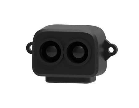
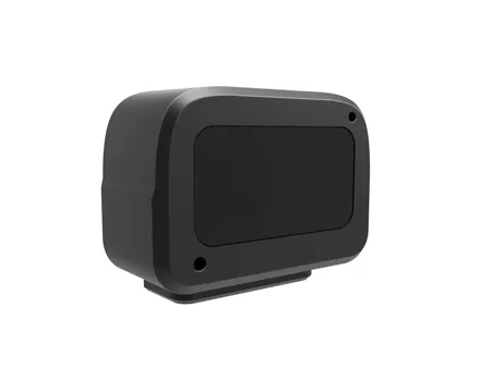
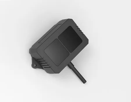
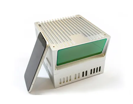
SentiAcu’s published portfolio includes single-point LiDAR, laser scanning measurement, pixel-array LiDAR, and radio-frequency sensing categories. These technologies can support different layers of an airborne perception architecture. A compact single-point module may be appropriate when the system needs direct distance along a line of sight with limited data overhead. A scanning or array sensor may be more suitable when the host requires spatial awareness, obstacle information, or scene geometry. RF sensing can provide complementary information in a multi-sensor architecture.
The correct product cannot be selected from range alone. A useful technical request should state the target, target reflectivity or material if known, minimum and maximum range, required accuracy, update rate, field of view or beam constraint, platform speed, operating temperature, available interface, size and weight limits, power supply, quantity, and required validation. SentiAcu can then discuss a configuration or identify where further testing is needed.
Published product specifications should be treated as configuration-specific information. Integrators should confirm the current datasheet, test conditions, interface definition, and environmental requirements before design freeze. This approach protects both sides from assuming that a family-level capability applies unchanged to every model.
An RFQ checklist is a structured set of technical and commercial inputs that allows suppliers to propose a comparable, testable EO/IR gimbal or sensing configuration.
| Requirement area | Information to provide | Why it matters |
|---|---|---|
| Mission | Inspection, search and rescue, mapping, perimeter awareness, infrastructure monitoring, or another lawful use | Determines sensor channels and operator workflow |
| Target | Approximate size, material, thermal contrast, reflectivity, motion, and background | Controls imaging and ranging feasibility |
| Geometry | Minimum/maximum slant range, altitude, viewing angle, and aircraft speed | Supports optics, range, and stabilization calculations |
| Output | Detection, recognition, identification, measurement, point cloud, video, metadata, or geolocation | Defines evidence required from the system |
| Platform | Available payload mass, mounting envelope, power, cooling, vibration, and center-of-gravity limits | Prevents an unairworthy or low-endurance configuration |
| Interfaces | Power bus, Ethernet/serial/video, protocol, time synchronization, coordinate frames | Reduces software and electrical redesign |
| Environment | Temperature, humidity, dust, water, altitude, storage, and electromagnetic conditions | Defines qualification and reliability needs |
| Verification | Required standards, test methods, target conditions, sample size, and acceptance thresholds | Makes proposals measurable and comparable |
| Commercial | Prototype quantity, annual quantity, schedule, documentation, customization, and support | Aligns development scope and lifecycle cost |
These FAQs answer common engineering and procurement questions about airborne EO/IR gimbals, ranging, stabilization, and integration.
An EO camera records reflected visible or near-visible light and is usually best for color, texture, markings, and fine daylight detail. An IR camera measures thermal radiation and can reveal temperature contrast at night or when visible contrast is weak. The best channel depends on the target, environment, range, optics, and required decision. Dual-channel systems need accurate boresight alignment so both sensors refer to the same line of sight.
No. Optical zoom narrows the field of view and can increase target pixels, but usable identification also depends on aperture, sensor resolution, atmospheric visibility, focus, contrast, stabilization, vibration, compression, and operator display quality. At long focal lengths, even small angular jitter can move the image by many pixels. Identification range should be validated with representative targets and conditions, not inferred from zoom ratio alone.
A rangefinder provides direct distance along the optical line of sight. That information can support inspection, focus or tracking assistance, altitude awareness, and better interpretation of target geometry. It does not by itself guarantee accurate coordinates. Positioning accuracy also depends on aircraft navigation, gimbal angles, boresight, timing, terrain data, and a complete error budget.
Specify the measurement method, operating mode, frequency band, focal length or field of view, disturbance profile, and whether the value is RMS, peak, or another statistic. Include dynamic behavior such as settling time, overshoot, tracking error, and performance under representative vibration. A single angular number without test conditions is insufficient for comparing systems.
Provide the target type and reflectivity, minimum and maximum range, required accuracy, update rate, beam or field-of-view limits, background light, atmosphere, platform speed, temperature range, size, weight, power, interface, and quantity. Also state how invalid or low-confidence measurements should be handled. These inputs are more useful than asking only for the longest advertised range.
Integration time varies with payload maturity, aircraft interfaces, customization, software ownership, environmental qualification, and flight-test scope. A straightforward installation using defined interfaces may progress quickly, while a multi-sensor, geolocating, customized payload can require substantial calibration and verification. The schedule should include requirements, interface control, bench testing, vibration and environmental work, restrained platform testing, progressive flight tests, and documentation.
Successful EO/IR gimbal integration is the result of matching mission evidence requirements to a verified sensor, stabilization, ranging, interface, and platform architecture.
The most important procurement decision is not the camera model; it is the definition of what the system must reliably tell the user. Once that outcome is clear, engineering teams can allocate image detail, thermal sensitivity, range, pointing stability, timing, mass, power, data, and environmental requirements across the payload. A smaller, well-integrated system will often outperform a feature-rich payload that lacks calibration, interface discipline, or realistic acceptance testing.
SentiAcu can support discussions involving compact LiDAR, range measurement, scanning perception, pixel-array sensing, and complementary RF sensing for airborne integration. To receive a technically relevant recommendation, provide the platform envelope, lawful application, target and distance, reflectivity or contrast assumptions, required accuracy and update rate, interfaces, environment, quantity, and verification method. That information enables a configuration discussion grounded in measurable performance rather than brochure comparisons.
The following independent sources provide authoritative background on LiDAR physics, remote sensing, and measurement constants used in this guide.
NASA Langley Research Center — LiDAR research overview: https://science.larc.nasa.gov/lidar/
NOAA Ocean Service — What is LiDAR?: https://oceanservice.noaa.gov/facts/lidar.html
NIST — Speed of light in vacuum: https://physics.nist.gov/cgi-bin/cuu/Value?c=