Choosing between a lidar scanner and a traditional coordinate measuring machine depends on what you measure, how fast you need results, and what accuracy level your process demands. For manufacturers focused on inspection speed, complex geometries, and digital quality workflows, modern laser scanning can be a powerful alternative or complement to touch-probe measurement. This guide compares both approaches and explains what to ask laser scanner manufacturers when evaluating a system for production inspection or lab metrology.
Understanding how each system collects data is the starting point for any tool selection decision.
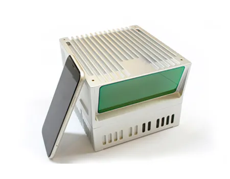
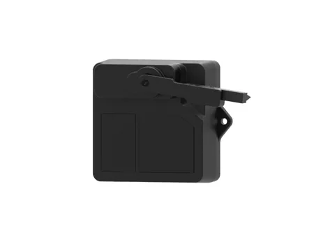
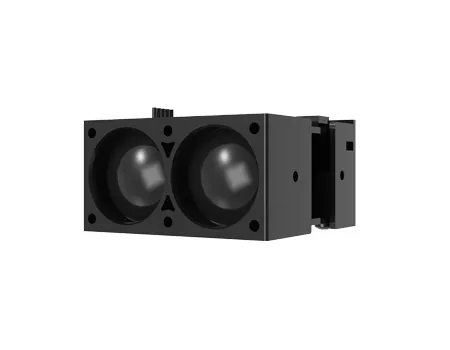
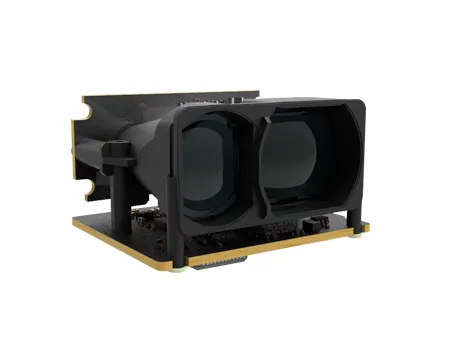
A lidar scanner or structured-light laser scanner projects a laser line or pattern onto the part surface and captures reflected data using a sensor array. The result is a dense point cloud — thousands to millions of measurement points per second — that represents the full surface geometry of the part. Measurement is non-contact; the scanner never touches the part.
A coordinate measuring machine uses a calibrated probe that physically contacts the part surface at defined points. Each contact event records a precise X, Y, Z coordinate. The machine builds up a feature measurement from a series of discrete contact points — a circle from three to five points, a plane from three or more, a hole location from a ring of contacts around the bore.
| Characteristic | Lidar Scanner | Touch-Probe CMM |
|---|---|---|
| Measurement principle | Non-contact; dense point cloud | Contact probing; discrete points |
| Data output | Full surface geometry; deviation map | Feature coordinates; GD&T values |
| Speed | Fast — full surface in seconds to minutes | Slower — point-by-point feature measurement |
| Surface coverage | Complete — every accessible surface captured | Selective — only probed features measured |
| Part contact | None — no risk of part marking or damage | Physical contact — considerations for soft or coated surfaces |
| Operator dependency | Lower for surface capture; higher for data interpretation | Moderate — program dependent; experienced CMM operators required |
| Best analogy | Photograph of the entire part | Ruler measurement of specific dimensions |
Neither technology is universally superior. The tool that is "right" is the one that matches the measurement task, the tolerance requirement, and the workflow it needs to fit into.
Before comparing numbers, it is important to understand what accuracy means for each technology type.
| Accuracy Term | Definition | Relevance |
|---|---|---|
| System accuracy | Overall measurement uncertainty of the complete system | The headline spec — compare carefully between suppliers |
| Repeatability | Variation when the same measurement is performed multiple times | Critical for process control and SPC applications |
| Resolution or point spacing | Minimum distinguishable distance between adjacent points | Affects ability to detect fine surface features |
| Environmental sensitivity | How temperature, vibration, and ambient light affect measurement | Factory floor vs. temperature-controlled lab comparison |
| Scenario | Why CMM Is Preferred |
|---|---|
| Tolerances below ±0.005 mm | Highest accuracy tier — CMM probing with calibrated standards |
| GD&T-critical feature measurement | Flatness, cylindricity, true position — discrete point CMM excels |
| Calibration traceability required | CMM calibration chains to national standards are well-established |
| Bore diameters and thread features | Contact probing captures internal geometry that scanners may miss |
| Legal or certification measurement | CMM measurement reports are the accepted standard in most industries |
| Scenario | Why Scanning Is Preferred |
|---|---|
| Large parts (automotive body, aerospace panel) | CMM travel range and cycle time become impractical; scanner covers the full surface |
| Freeform surfaces with no defined features | Point cloud comparison to CAD model reveals deviation across the entire form |
| High volume with fast cycle time | Scanner completes full surface inspection in a fraction of CMM program time |
| Reverse engineering | Dense surface data enables CAD reconstruction without defined feature references |
| Fragile or soft parts | Non-contact scanning eliminates contact deformation risk |
| Complex surface topology | Undercuts, organic shapes, and compound curves captured without fixture repositioning |
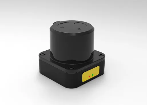
The total inspection cycle time is not just the measurement time — it includes setup, alignment, data processing, and report generation. Understanding where time is consumed in each workflow is critical for production integration decisions.
| Workflow Stage | CMM | Laser Scanner |
|---|---|---|
| Part fixturing | Precise datum fixturing required | Flexible — often uses reference targets or features |
| Alignment | Coordinate system establishment from datum contacts | Best-fit or RPS alignment to CAD model |
| Measurement execution | Program runs point by point — time scales with feature count | Scan pass captures full surface — time scales with part size |
| Data processing | Feature extraction is immediate — results in real time | Point cloud processing and surface comparison requires compute time |
| Report generation | Automated from CMM software — fast | Deviation maps, section analysis, GD&T extraction — more setup required initially |
Modern laser scanner systems from leading laser scanner manufacturers are increasingly designed for production integration:
Inline scanning cells mounted on robots or gantry systems for 100% part inspection
Nearline scanning stations with quick-load fixtures for sample-based inspection at takt time
Pass/fail decision output directly to production control systems
Integration with SPC software for real-time process trend monitoring
| Question | Why It Matters |
|---|---|
| What CAD file formats does the software accept? | Confirms compatibility with your design and CAD environment |
| Can the software extract GD&T values from the point cloud? | Determines whether scan data can replace or supplement CMM measurement reports |
| What SPC or MES integration is available? | Affects whether scan data feeds your quality management system directly |
| How are deviation maps and inspection reports formatted? | Determines whether outputs meet customer or certification requirements |
| What is the typical learning curve for a new operator? | Affects training investment and deployment speed |
| Industry | Typical Application | Why Scanning Fits |
|---|---|---|
| Automotive body and trim | Panel gap and flush inspection, stamping variation, body-in-white deviation | Large surface area; full-field deviation map required |
| Aerospace composites | Skin panel thickness, surface profile, ply inspection | Complex curves; non-contact for sensitive materials |
| Precision machining | First article inspection, casting-to-finish comparison | Fast full-surface verification against CAD |
| Tooling and mold | Cavity surface inspection, wear tracking over tool life | Dense point cloud captures subtle surface changes |
| Castings and forgings | Material distribution verification, core shift detection | Freeform geometry with no defined feature references |
| Additive manufacturing | Layer deviation, support removal verification, surface roughness mapping | Complex topology; freeform surfaces throughout |
Part size: larger parts favor scanning; small, prismatic, tight-tolerance parts may favor CMM
Surface reflectivity: highly reflective or transparent surfaces challenge most optical scanners — confirm with laser scanner manufacturers before purchase
Inspection frequency: high-volume production favors fast scanning; low-volume certification work may favor CMM
Cycle time requirement: confirm scan plus processing time fits your available inspection window
Many quality teams achieve the best of both technologies by combining them in one workflow. The scanning system captures full-field surface deviation quickly — identifying any area of concern across the entire part. The CMM then confirms specific critical features and datums with the highest accuracy. This approach reduces CMM program time by focusing contact measurement only where it is most needed, while giving engineers full surface visibility from the scan data.
| Specification | What to Ask | Why It Matters |
|---|---|---|
| Accuracy class | Volumetric accuracy in µm over defined measuring volume | Primary performance spec — compare on same volume basis |
| Working distance | Optimal stand-off range from scanner to part surface | Must match your fixture and part geometry |
| Field of view | Width and depth of scan stripe or area | Determines scan path planning and number of passes |
| Scan speed | Points per second or lines per second | Affects total scan time for your part size |
| Laser safety class | Class 2 or Class 3R — operator safety requirements | Affects whether safety enclosure or eyewear is required |
| Calibration method | How the system is calibrated and how often | Affects ongoing calibration cost and traceability |
| Temperature compensation | Does the system correct for thermal expansion? | Critical for factory floor use outside temperature-controlled lab |
Do not buy any metrology system without measuring your actual parts under your actual conditions. A structured trial plan should include:
Scan a representative sample of your most challenging parts — not the easiest ones
Run side-by-side comparison with your existing CMM on the same features
Compare deviation results and confirm the scanner meets your tolerance requirement
Test the full workflow from scan to report — not just the scan step
Run the trial with your own operators, not only vendor demonstrators
| Factor | What to Confirm |
|---|---|
| Training | Initial training included; ongoing training available |
| Warranty | Duration and what is covered — hardware, software, calibration artifacts |
| Service response | On-site response time; loaner unit policy during repair |
| Software updates | Frequency and cost of software updates and new features |
| Local support | In-country or in-region service and applications engineering |
A lidar scanner delivers speed and full-field surface coverage that a traditional CMM cannot match — making it the stronger choice for large parts, complex geometries, freeform surfaces, and high-volume production inspection. A CMM remains the preferred tool for ultra-tight tolerances, GD&T-critical feature measurement, and certified measurement applications where traceability is the primary requirement. Many teams get the best results by combining both: scan for fast full-field insight and process feedback, then validate critical features and datums with a CMM.
Q1: Is a lidar scanner accurate enough to replace a CMM?
It depends on your tolerance requirements and measurement application. Modern laser scanners can meet the accuracy demands of many production inspection tasks, particularly for surface form, deviation mapping, and first article inspection of complex geometries. For the tightest tolerances — below ±0.005 mm — and for certified GD&T feature measurement with full traceability, CMMs remain the standard. The most effective approach is often to use both tools for the tasks each does best.
Q2: What is the biggest advantage of using a lidar scanner in a manufacturing metrology workflow?
Speed and full-field surface coverage. A scanner captures dense point cloud data across the entire accessible surface of a part in a fraction of the time a CMM would take to probe an equivalent set of features. This makes scanning particularly valuable for complex geometry, reverse engineering, deviation mapping against CAD, and high-volume production inspection where cycle time is constrained.
Q3: What should I ask laser scanner manufacturers before making a purchase decision?
Ask for verified accuracy specifications on your part size and geometry — not just the best-case spec. Confirm the calibration method and traceability chain. Request a demonstration of the complete workflow from scan to report, not just the scanning step. Ask about software integration with your CAD, SPC, and quality management systems. Confirm training, warranty, and service response terms. And insist on a trial measurement with your actual parts before committing.
Q4: When is a traditional CMM the better metrology choice?
CMMs are preferred for ultra-tight tolerance measurement where system accuracy below ±0.002 to ±0.005 mm is required, for GD&T-controlled features where contact probing provides the most reliable data, for internal geometries such as bores and threads that optical systems struggle to capture, and for any application where certified, traceable measurement documentation is required by the customer or a regulatory standard.
Q5: Can a manufacturing quality team use both a scanner and a CMM in the same workflow?
Yes — and this is increasingly the recommended approach for teams that need both speed and precision. The scanner performs fast full-field surface inspection and identifies any areas of concern across the entire part. The CMM then confirms specific critical features, datums, and tight-tolerance dimensions with contact probing accuracy. This combination reduces total CMM program time by focusing contact measurement only where it is most needed, while providing engineers with complete surface visibility from the scan data.