Selecting a UAV LiDAR system begins with a mission outcome, not a sensor category. A mapping aircraft, a terrain-following drone, an autonomous landing platform, and a navigation system operating where GNSS is unreliable may all use LiDAR, but they need very different measurements, fields of view, update rates, data pipelines, and verification methods. Treating these applications as interchangeable is one of the fastest ways to buy the wrong payload.
This guide provides a decision framework for UAV manufacturers, survey teams, robotics engineers, system integrators, and technical buyers. It explains how single-point ranging, two-dimensional scanning, pixel-array sensing, and three-dimensional scanning can support different flight functions. It also connects sensor specifications to aircraft limits, flight planning, data processing, safety, and lifecycle cost.
SentiAcu, a sensing technology brand associated with NeoFlux Limited, supplies perception products across single-point LiDAR, laser scanning measurement, pixel-array LiDAR, and radio-frequency sensing categories. Rather than recommending one technology for every project, this guide shows how to define the measurement problem first and then identify the smallest, most testable sensor architecture that can solve it.
A UAV LiDAR system is an airborne sensing architecture that measures distance with light and combines the resulting ranges with platform position, attitude, timing, and processing to support mapping, navigation, landing, inspection, or obstacle awareness.
LiDAR stands for light detection and ranging. In a time-of-flight implementation, the sensor transmits light and measures how long the return takes to arrive after reflecting from a surface. Because the light travels to the target and back, range is related to half of the measured round-trip travel time. Real systems must also account for detector response, signal processing, atmospheric attenuation, target reflectivity, beam geometry, background light, and timing uncertainty.
A complete UAV system contains more than the ranging sensor. Depending on the task, it may include GNSS, an inertial measurement unit, a navigation computer, a gimbal or fixed mount, a camera, data storage, an onboard processor, power conditioning, time synchronization, and post-processing software. Mapping additionally requires georeferencing and calibration. Autonomous navigation requires low-latency perception, health monitoring, and a safe response when the measurement is invalid.
The term uav lidar therefore describes a system-level capability, not just a box with a maximum range. The value of the system is determined by whether the measurement arrives with the right coverage, accuracy, update rate, latency, coordinate frame, confidence, and reliability for the intended flight function.
Mission-based selection links each sensor requirement to an operational decision such as generating a surface model, maintaining altitude, detecting an obstacle, or estimating motion when satellite navigation is degraded.
Begin by writing one sentence that states what the aircraft must do. “Collect LiDAR data” is too vague. Better statements include: “Generate a georeferenced terrain model with a defined vertical accuracy,” “Maintain a commanded clearance over variable ground,” “Confirm height above a landing zone during the final descent,” or “Estimate local motion through a warehouse without GNSS.” Each statement leads to different acceptance tests.
Next define the consequence of a missed, late, or incorrect measurement. A post-processed survey can reject a poor flight line and repeat it. A real-time landing controller cannot wait for offline correction. This distinction determines the required latency, redundancy, invalid-data handling, diagnostics, and development assurance. Real-time flight functions need more than nominal sensor accuracy; they need predictable behavior during dust, water, low-reflectivity surfaces, strong sunlight, attitude changes, and partial field-of-view obstruction.
Finally, define the operating geometry. Important variables include altitude above ground, slant range, aircraft speed, climb and descent rates, bank and pitch angles, terrain slope, obstacle size, surface reflectivity, vegetation, expected weather, and the mounting orientation. A sensor that measures 100 meters on a favorable vertical target may not provide the same margin on dark terrain at an oblique angle.
A UAV LiDAR decision tree selects the minimum sensor geometry needed to answer the mission question, ranging from one line-of-sight distance to a dense three-dimensional point cloud.
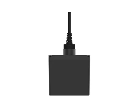
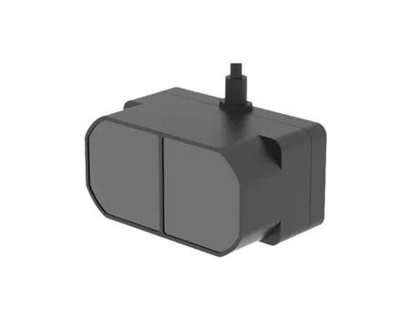
A single point lidar measures along one narrow direction. It can be a strong fit for height above ground, final-approach ranging, line-of-sight distance, focus assistance, payload cueing, or another task where the system already knows where to look. It produces less data than a scanner and can be compact, but it cannot independently describe the surrounding surface outside its beam.
Single-point sensors should be assessed for minimum and maximum range, target reflectivity, accuracy, repeatability, update rate, beam divergence, receiver field, sunlight tolerance, multi-return behavior, invalid-return reporting, size, weight, power, interface, and temperature. A downward-facing installation also needs to consider aircraft attitude: the sensor measures slant range along its beam, not automatically vertical height.
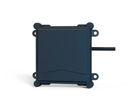
A two-dimensional scanner measures many angles within a plane. It can support terrain profiles, corridor awareness, obstacle cross-sections, localization, or scanning measurement around a platform. Compared with a single point, it provides spatial context. Compared with a full 3D scanner, it can reduce data volume and processing demand.
Selection depends on angular field of view, angular resolution, scan rate, point rate, range on relevant surfaces, accuracy, latency, and how the scan plane is oriented relative to aircraft motion. A forward-looking plane can detect obstacles in a slice but may miss objects above or below it. A downward-looking plane can build a terrain profile across the flight path, but bank angle and vegetation affect the returns.
A pixel-array device measures a grid of directions and produces depth arranged similarly to an image. It can support short- to medium-range obstacle awareness, landing-zone shape assessment, vehicle or robot perception, and local scene understanding. The output may be easier to integrate into image-like processing than an irregular point stream, but the buyer must evaluate pixel count, field of view, frame rate, range, missing-data behavior, and sunlight performance.
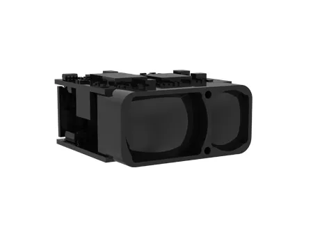
A compact 3d lidar sensor can be appropriate when the application needs simultaneous spatial coverage without the mechanical or data burden of a high-density survey scanner. It should not be assumed to replace a long-range mapping payload. Pixel count and field of view determine angular sampling, while target size and distance determine how many pixels represent an obstacle.
Surveying, digital twins, volumetric measurement, forestry, corridor mapping, and detailed terrain modeling may require a three-dimensional point cloud. The airborne system then needs a scanner, precise navigation, time synchronization, calibration, storage, flight-planning software, and post-processing. Point density depends on altitude, speed, scan pattern, pulse rate, field of view, overlap, and surface visibility.
A dense point cloud is not automatically accurate. System accuracy depends on range error, GNSS/INS performance, lever-arm measurement, boresight calibration, timestamp alignment, trajectory processing, strip adjustment, and ground control or independent checkpoints where required. Buyers should evaluate the complete workflow rather than compare only points per second.
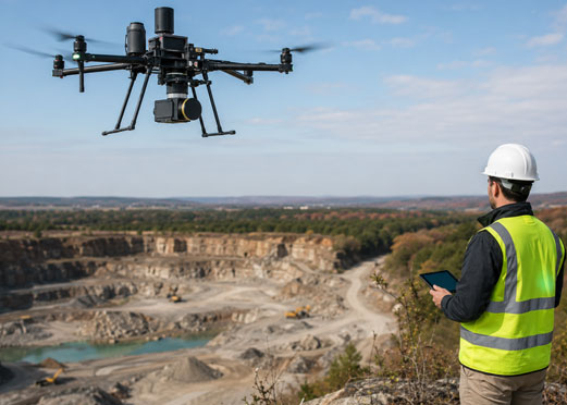
UAV LiDAR mapping converts time-synchronized range measurements and aircraft trajectory data into georeferenced point clouds, surface models, terrain products, or asset measurements.
The workflow begins before flight. The team defines the coordinate reference system, required horizontal and vertical accuracy, point density, ground sampling needs, overlap, vegetation penetration objectives, and deliverables. It then selects altitude, speed, flight-line spacing, scan angle, and control strategy. These choices must be compatible with local aviation rules, site access, terrain, weather, and the aircraft’s endurance.
Point density can be estimated from sensor point rate, scan pattern, altitude, speed, and overlap, but published point rate alone is insufficient. Some points may fall outside the useful swath, be filtered by range limits, strike vegetation, or be lost on low-return surfaces. A useful plan includes a margin for turns, variable terrain, wind, and data-quality rejection.
Georeferencing is a major source of error. The scanner origin is offset from the GNSS antenna and inertial unit by a lever arm, while its axes are rotated relative to the navigation frame by boresight angles. Small angular errors can become large position errors at altitude. These values should be measured, calibrated, documented, and checked after mechanical changes.
Timing is equally important. A point must be associated with the correct aircraft position and attitude. At 20 meters per second, a timing error of 10 milliseconds corresponds to 0.2 meter of along-track movement before attitude effects are considered. This simple calculation shows why timestamp architecture and synchronization should be part of the sensor specification.
Quality assurance should use independent checkpoints and a documented statistical method appropriate to the project. Reported accuracy should distinguish relative precision within a strip from absolute accuracy in the required coordinate system. Teams should retain flight logs, trajectory quality, calibration versions, processing parameters, rejected areas, and checkpoint results so the deliverable can be audited.
Terrain-following LiDAR measures the ground or nearby surface in real time so a flight controller can maintain a planned clearance or adapt to changing topography.
Terrain following needs fast, reliable information with low and bounded latency. A downward single-point sensor may be enough over relatively smooth, open ground when aircraft attitude is controlled. Complex terrain, slopes, vegetation, sudden edges, or forward motion may require a scanning profile or multiple directions so the controller can anticipate changes rather than react after passing over them.
The system must define what “ground” means. Over vegetation, the first return may come from the canopy and a later return from the ground. Over water, specular reflection can direct energy away from the receiver. Over dark asphalt or low-reflectivity soil, signal strength can fall. Dust, fog, rain, snow, and strong background light may reduce valid range. The controller should therefore use validity and confidence, not only a numeric distance.
Aircraft attitude transforms line-of-sight range into vertical or normal distance. If the sensor is rigidly mounted, pitch and roll rotate the beam. The navigation computer needs the sensor mounting angles and current aircraft attitude to interpret the measurement. If the sensor is stabilized, the system must know the commanded and measured pointing direction with accurate timestamps.
Control design should include filtering without excessive delay. Heavy smoothing can remove noise but cause the aircraft to react too late. A robust implementation combines physical limits, temporal consistency, terrain models where available, additional sensors, and a safe fallback when LiDAR is unavailable. Validation should include slopes, drop-offs, vegetation transitions, dark surfaces, reflective surfaces, and intentional invalid readings.
Autonomous landing LiDAR provides height, descent, surface, or obstacle information during approach and touchdown so the aircraft can reduce uncertainty near the ground.
The final phase of flight has unique geometry. The required range may be shorter than in mapping, but update rate, minimum range, latency, and invalid-data behavior become critical. A sensor that performs well at 100 meters but cannot measure reliably below one meter may be unsuitable for touchdown support. The landing logic should define the transition between barometric altitude, GNSS altitude, LiDAR height, visual odometry, and contact detection.
A single downward range can support height above a suitable surface. A depth image or scanning pattern can additionally reveal slope, obstacles, holes, vegetation, or uneven terrain. The required spatial coverage depends on landing-gear footprint, aircraft drift, descent rate, and acceptable surface conditions. A narrow beam may land between obstacles it never saw, while a very wide field may include unwanted structures outside the touchdown zone.
Rotor wash can disturb dust, grass, snow, or water. These particles may create strong near returns that obscure the ground. Testing should reproduce the actual aircraft, rotor configuration, descent rate, and surface. Algorithms may use temporal consistency, multiple returns, spatial filtering, or sensor fusion, but every rejection rule can also remove real obstacles. The acceptance plan should include both nuisance-return rejection and obstacle-preservation tests.
Landing-zone assessment must be tied to a decision. If the system claims to detect a slope, define the maximum allowed slope, area used for fitting, required valid pixels, and response to partial coverage. If it claims obstacle detection, define the minimum obstacle size, contrast or reflectivity, distance, field location, and probability of detection. These definitions make software and hardware requirements testable.
GNSS-denied LiDAR navigation estimates aircraft motion or position by matching sequential range observations to local geometry when satellite navigation is unavailable, unreliable, or intentionally not used.
LiDAR odometry and simultaneous localization and mapping compare scans over time to estimate movement and build a map. The method needs geometric features and sufficient overlap between observations. Long, uniform corridors, open fields, water, fog, glass, repetitive structures, or sparse scenes can reduce observability. A system that works in a feature-rich warehouse may not work over flat terrain.
The sensor geometry should match aircraft motion. A 2D scanner can support planar localization in some indoor or constrained environments, but a flying vehicle moves in six degrees of freedom. Three-dimensional coverage or additional sensors may be necessary to observe roll, pitch, yaw, and translation. The architecture often fuses LiDAR with an inertial measurement unit, camera, barometer, radar, or other sources.
Latency and compute load matter. Scan matching, filtering, mapping, and optimization require processing. If the output arrives late, the flight controller acts on an old state. The system should report processing time, update rate, covariance or confidence, failure detection, and recovery behavior. A demo path should not substitute for a statistically meaningful dataset covering the intended environment.
Map management also affects deployment. Some systems build a map online; others localize against a prebuilt map. Prebuilt maps need version control and change management. Online mapping needs memory and loop-closure strategies. Security-sensitive facilities may restrict data storage or transfer, so the data architecture should be agreed during design.
Comparing UAV LiDAR sensor types means evaluating the measurement geometry, range, update behavior, data load, integration burden, and failure modes against a defined mission.
| Sensor type | Measurement output | Typical strengths | Typical limitations | Best-fit UAV functions |
|---|---|---|---|---|
| Single-point ToF LiDAR | One range per measurement direction | Compact, lower data load, direct distance, potentially long range depending on design | No surrounding geometry; sensitive to pointing and target return | Altitude, landing range, line-of-sight distance, gimbal ranging |
| 2D laser scanner | Range profile across one angular plane | Spatial context with moderate data and processing | Objects outside the scan plane may be missed | Terrain profile, corridor awareness, SLAM in constrained scenes |
| Pixel-array dToF | Depth image across a fixed field of view | Simultaneous local 3D coverage, no mechanical sweep in the array itself | Pixel count, range, sunlight, and missing-data behavior constrain detail | Landing-zone assessment, obstacle awareness, local scene perception |
| Full 3D scanning LiDAR | Dense point cloud over a volume | Detailed geometry and mapping capability | Higher mass, power, cost, data, calibration, and post-processing | Surveying, digital twins, forestry, infrastructure mapping |
| Multi-sensor fusion | LiDAR combined with camera, IMU, GNSS, radar, or other sensing | Complementary information and improved robustness when designed correctly | Time, coordinate, uncertainty, software, and validation complexity | Autonomous navigation and demanding all-condition awareness |
The table is a functional comparison, not a universal range ranking. Actual performance varies by model, wavelength, receiver, optics, target, atmosphere, sunlight, scan pattern, and processing. Buyers should request configuration-specific test data.
These four specifications describe how far a UAV LiDAR can measure, how close the result is to a reference, how finely it samples space, and how often usable measurements become available.
Range must be specified with target reflectivity, size, angle, atmosphere, background light, and probability of valid detection. A maximum range on a large reflective target is not equivalent to range on dark vegetation or a small cable. Minimum range is equally important for landing and close obstacle avoidance.
Accuracy is closeness to a reference, while precision or repeatability describes the spread of repeated measurements. A sensor can be repeatable but biased. Mapping accuracy additionally includes navigation, calibration, timing, and processing errors. For control, latency and outliers may matter as much as static accuracy.
Resolution can refer to range resolution, angular resolution, pixel spacing, or final ground point spacing. These are different. Angular sampling determines how target detail grows with distance. For example, a 0.2-degree angular interval corresponds to roughly 0.35 meter spacing at 100 meters under a small-angle approximation. That does not include beam divergence or motion.
Update rate can mean pulse rate, point rate, scan rate, frame rate, or output message rate. A sensor may emit many points per second but update a particular direction less frequently. Real-time control should use the age and latency of the relevant measurement, not the largest number on the datasheet.
The UAV LiDAR data pipeline is the sequence from mission planning and sensor timing through flight collection, trajectory processing, point-cloud generation, calibration, quality control, and final deliverables.
Define deliverables and accuracy. Specify point cloud, bare-earth model, surface model, contours, asset measurements, or another output, together with coordinate system and accuracy criteria.
Plan geometry. Select altitude, speed, line spacing, overlap, scan angle, and turn margins based on terrain, point density, sensor coverage, and regulation.
Survey control where required. Establish checkpoints or control using an appropriate method and independent quality process.
Synchronize sensors. Confirm GNSS, IMU, scanner, camera, and computer time before collection. Record status and timing health.
Collect with quality monitoring. Watch trajectory quality, storage, sensor temperature, dropped packets, GNSS status, and coverage during flight.
Process trajectory. Use the selected GNSS/INS workflow, corrections, lever arms, and quality checks.
Generate the point cloud. Apply range measurements, scan angles, trajectory, boresight, and coordinate transformations.
Calibrate and align strips. Check overlapping flight lines, systematic roll/pitch/yaw patterns, and height differences.
Classify and derive products. Separate ground, vegetation, buildings, or assets according to project requirements.
Validate independently. Compare with checkpoints, document statistics, inspect gaps, and report limitations.
Data governance should cover raw files, processed products, coordinate metadata, software versions, calibration, naming, retention, security, and customer delivery. A technically accurate point cloud can still be unusable if coordinate reference, units, or version history are unclear.
UAV LiDAR integration is the process of mounting, powering, synchronizing, communicating with, and interpreting the sensor without degrading aircraft safety or measurement quality.
Mechanical design should account for sensor mass, center of gravity, structural stiffness, field-of-view obstruction, vibration, airflow, dust, water, heat, and access for service. A downward sensor should not be blocked by landing gear or payload doors. A forward sensor should avoid propeller arcs and reflections from the aircraft structure. Reflective nearby surfaces can create persistent close returns.
Electrical design should include input voltage range, startup and peak current, power conditioning, grounding, electromagnetic compatibility, connector retention, and failure isolation. The aircraft should know when the sensor has booted, when measurements are valid, and when a fault occurs. Brownouts or intermittent connectors can create data gaps that look like environmental failures.
Software integration requires an interface control document. Define packet formats, units, endian convention, timestamps, coordinate frames, status bits, invalid values, sequence counters, configuration commands, logging, network recovery, firmware update, and cybersecurity. A prototype that depends on undocumented settings is difficult to manufacture or maintain.
Calibration includes lever arms, mounting angles, boresight, range bias, temperature behavior, and synchronization. These values should be associated with hardware serial numbers and configuration versions. If a sensor is removed and reinstalled, the maintenance procedure should define which calibrations must be repeated.
Environmental validation demonstrates that the UAV LiDAR continues to provide defined performance, diagnostics, or safe failure behavior under the temperature, vibration, shock, moisture, dust, light, and electromagnetic conditions of its intended use.
Temperature can affect laser output, detector sensitivity, timing, optics, alignment, processor load, and condensation. Test both functional operation and measurement performance across the required range. A product may remain powered at an extreme temperature while accuracy, valid-return rate, or startup time changes.
Vibration testing should reflect the aircraft and mounting system. Multirotor platforms, fixed-wing aircraft, and rotorcraft have different spectra. Measure the sensor on the intended isolator and structural interface. A scanner with moving components may have additional sensitivity to vibration orientation.
Optical environments require dedicated tests. Strong sunlight can increase detector background. Dark or angled surfaces reduce returns. Glass and water can produce unexpected paths or weak diffuse reflection. Dust, fog, rain, and snow can generate near returns and attenuation. Validation should record not only average error but also valid-measurement rate, outliers, false obstacles, and recovery time.
Reliability also includes diagnostics and lifecycle support. Useful capabilities include temperature reporting, supply monitoring, link status, error codes, internal test, configuration readback, event logs, and controlled firmware updates. Procurement should ask how failures are detected, what data are preserved, and how units are recalibrated or repaired.
Total cost of ownership includes the sensor, navigation hardware, compute, storage, mounting, power, software, calibration, aircraft integration, testing, training, processing, maintenance, and repeated operations required to deliver a usable result.
A lower sensor price does not guarantee a lower project cost. A device with an undocumented protocol may require more software engineering. A heavy payload may force a larger aircraft. A scanner with high data volume may require faster storage, more compute, and longer processing. A system with weak diagnostics may increase field failures and repeat flights.
Compare proposals using the same scope. Separate non-recurring engineering from unit price. Identify included and optional software, licenses, GNSS/INS, cables, mounts, calibration, documentation, training, spares, warranty, and technical support. Ask whether future firmware or format changes affect compatibility.
For mapping, cost per successful deliverable can be more meaningful than hardware price. Consider acres or kilometers covered per flight, repeat-flight rate, processing time, staffing, control requirements, data quality, and project acceptance. For autonomous functions, include safety validation, software assurance, redundancy, and lifecycle configuration control.
A supplier scorecard converts technical, quality, integration, and commercial requirements into weighted evidence so competing UAV LiDAR proposals can be compared consistently.
| Category | Suggested weight | Evidence to request |
|---|---|---|
| Mission performance | 25% | Range, accuracy, valid-return rate, resolution, latency, and target-condition test data |
| Platform fit | 15% | Mass, dimensions, power, thermal behavior, vibration, mounting and field of view |
| Interfaces and software | 15% | Interface control document, sample data, SDK/API, time synchronization, diagnostics |
| Environmental reliability | 15% | Test reports, methods, operating limits, failure behavior and qualification status |
| Calibration and data quality | 10% | Calibration process, traceability, serial-number configuration, acceptance method |
| Manufacturing and quality | 10% | Change control, inspection, lot traceability, nonconformance and corrective action |
| Lifecycle support | 5% | Firmware policy, repairs, recalibration, spares, documentation and response process |
| Commercial fit | 5% | Prototype and production price, lead time, MOQ, payment, warranty and schedule risk |
Weights should change by project. A survey company may assign more weight to calibration, trajectory integration, and processing. An autonomous aircraft program may assign more to latency, diagnostics, environmental behavior, and safe failure. The important practice is to score evidence, not sales language.
SentiAcu supports UAV LiDAR projects by helping integrators match sensing geometry, range, data output, interfaces, and platform constraints to a defined airborne measurement task.
The SentiAcu portfolio spans single-point LiDAR for direct range measurement, laser scanning measurement for profile or spatial scanning, pixel-array LiDAR for depth imaging, and complementary RF sensing. This range of categories allows an engineering discussion to begin with the information needed rather than forcing every application into one sensor type.
For a productive evaluation, provide the aircraft type, lawful mission, altitude and speed, target or terrain, minimum and maximum range, expected reflectivity, required accuracy, angular or spatial coverage, update rate, latency, interface, power, size and weight budget, environment, prototype quantity, production forecast, and acceptance method. If the project involves mapping, also provide required point density, coordinate accuracy, swath, GNSS/INS plan, and deliverables. If it involves landing or navigation, define fallback behavior and the maximum age of a valid measurement.
SentiAcu can use these inputs to discuss a suitable product family or testing path. The current model datasheet and configuration-specific conditions should be confirmed before mechanical design or procurement approval. Where standard data do not represent the target surface or environment, a representative sample test is more valuable than extrapolating from an ideal-range claim.
These FAQs provide concise answers to common questions about selecting, integrating, and operating LiDAR on unmanned aircraft.
The best LiDAR is the smallest system that meets the defined mission with adequate margin. Single-point LiDAR may suit altitude or line-of-sight ranging, 2D scanning may suit terrain profiles or constrained SLAM, pixel-array LiDAR may suit local obstacle or landing-zone perception, and 3D scanning may suit detailed mapping. Compare target conditions, range, accuracy, field of view, update rate, latency, mass, power, interface, environment, and validation evidence.
Mapping accuracy depends on the complete system: range sensor, GNSS/INS, timing, lever-arm measurement, boresight calibration, flight geometry, trajectory processing, strip adjustment, control or checkpoints, and surface conditions. Sensor range accuracy alone is not the final map accuracy. A project should define horizontal and vertical accuracy, confidence level, coordinate system, independent checkpoints, and the statistical method used for acceptance.
Yes, a single-point sensor can support height measurement during landing when the surface, aircraft attitude, beam coverage, minimum range, update rate, latency, and invalid-return behavior are suitable. It does not independently assess slope or obstacles outside the beam. More complex landing-zone assessment may require a scan, depth image, camera, radar, or sensor fusion together with a safe fallback strategy.
Performance can be challenging on these surfaces. Water may reflect specularly away from the receiver, snow can create strong or variable returns, and dark ground can return less optical energy. Angle, wavelength, beam, receiver, sunlight, weather, and processing all matter. Buyers should request testing on representative surfaces and include invalid-data handling rather than assuming the advertised maximum range applies everywhere.
Data rate depends on point rate, attributes per point, timestamp format, scan metadata, compression, frame rate, and whether raw waveforms or images are stored. The link and storage should include margin for headers, diagnostics, retransmission, and peak bursts. Real-time systems must also consider processing latency and network determinism, while mapping systems must plan total storage per flight and post-processing throughput.
Include the aircraft, mission, altitude, speed, terrain or target, reflectivity, range, accuracy, field of view, angular or point density, update rate, latency, interface, time synchronization, power, size, weight, temperature, weather exposure, quantity, schedule, required documentation, and acceptance tests. For mapping, add deliverables and coordinate accuracy. For flight control, add failure response and maximum measurement age.
A successful UAV LiDAR selection converts an operational task into measurable sensor, navigation, integration, and validation requirements before choosing hardware.
Mapping, terrain following, autonomous landing, and GNSS-denied navigation may all use LiDAR, but they are not the same engineering problem. Mapping emphasizes georeferencing, calibration, point density, and deliverable accuracy. Terrain following emphasizes timely ground interpretation. Landing emphasizes minimum range, local surface awareness, and failure behavior. GNSS-denied navigation emphasizes geometry, scan matching, latency, observability, and sensor fusion.
The best procurement process therefore begins with a mission sentence, an error or risk budget, representative surfaces, platform constraints, and acceptance tests. It compares complete systems rather than headline range or point rate. It also accounts for data, calibration, software, environmental reliability, maintenance, and lifecycle support.
SentiAcu can discuss single-point, scanning, pixel-array, and complementary sensing options for airborne platforms. Share the aircraft envelope, measurement task, target and environment, required output, interfaces, schedule, and validation method to begin a configuration-focused conversation.
Definition: These independent references provide regulatory and scientific background relevant to civil UAV operations and LiDAR remote sensing.
Federal Aviation Administration — Small Unmanned Aircraft Systems Regulations, Part 107: https://www.faa.gov/newsroom/small-unmanned-aircraft-systems-uas-regulations-part-107
NOAA Ocean Service — What is LiDAR?: https://oceanservice.noaa.gov/facts/lidar.html
NASA Earth Science Data Systems — Uncrewed Aerial Vehicle platform overview: https://impact.earthdata.nasa.gov/casei/platform/UAV/