LiDAR datasheets contain numbers that look easy to compare but often describe different test conditions, measurement geometries, and system boundaries. A 1,500-meter maximum range on one target cannot be compared directly with a 20-meter specification on a 10% reflectivity target. A point rate is not the same as a frame rate. Angular resolution is not the same as range accuracy. Sensor price is not the same as the installed cost of a working perception system.
This engineering buyer’s guide explains how to interpret the specifications that most strongly affect LiDAR selection: range, accuracy, precision, resolution, field of view, point or frame rate, wavelength, reflectivity, latency, environmental limits, and price. It is intended for product designers, robotics teams, UAV integrators, industrial automation engineers, surveying professionals, and procurement managers who need comparable evidence rather than unqualified marketing claims.
SentiAcu, a sensing technology brand associated with NeoFlux Limited, offers multiple perception categories, including single-point LiDAR, laser scanning measurement, pixel-array LiDAR, and radio-frequency sensing. Examples from the published SentiAcu portfolio are used to show why specifications must be tied to a model and test condition. Buyers should always confirm the latest datasheet and configuration before making a design commitment.
A LiDAR sensor measures distance by transmitting light, detecting reflected energy, and converting the return into one or more ranges that describe a point, profile, depth image, or three-dimensional scene.
LiDAR is an acronym for light detection and ranging. Many systems use direct time of flight: a short optical signal travels from the transmitter to the target and back to a receiver. The measured round-trip time is converted into distance. Other architectures may use phase, frequency modulation, or different detection methods, but every practical system must distinguish the desired return from background light, noise, reflections, and internal delay.
The exact speed of light in vacuum is 299,792,458 meters per second. A simplified direct time-of-flight equation is distance equals the speed of light multiplied by measured round-trip time, divided by two. In air, precise metrology may account for refractive index and environmental conditions. Commercial sensor accuracy also depends on timing electronics, pulse shape, detector response, calibration, algorithms, target properties, and signal-to-noise ratio.
A lidar sensor can output one range, a line of ranges, a depth grid, or a point cloud. The measurement geometry determines what the system can know. One range may be ideal for altitude or target distance. A scan profile may support SLAM or cross-sectional awareness. A depth array may provide local obstacle geometry. A dense scanner may produce detailed maps. The correct comparison begins by matching output geometry to the decision the host system must make. A 3d laser scanner or depth-sensing system is most useful when the application genuinely needs spatial geometry rather than a single distance.
LiDAR sensor range is the interval between the nearest and farthest target distances at which the sensor produces measurements that meet stated validity and accuracy conditions.
Maximum range is one of the most misused LiDAR specifications. It depends on transmitted optical energy, beam divergence, receiver aperture, detector sensitivity, wavelength, target area, target reflectivity, target angle, atmosphere, background light, processing, and the required probability of detection. A range number without a target and condition is incomplete.
Reflectivity is especially important. A white reference target may return far more energy than black rubber, dark soil, asphalt, vegetation, or a small object. Surface angle matters because a diffuse target sends some light in many directions, while a specular surface can reflect most energy away from the receiver. Target size also matters when the beam becomes larger than the object at distance.
Beam divergence describes how the transmitted beam expands. Under a simple approximation, a 1-milliradian full-angle divergence creates a spot about 1 meter wide at 1 kilometer. The exact definition may use full angle, half angle, or a specified intensity boundary, so datasheets should be compared carefully. A larger spot can improve coverage but may combine returns from target and background. A smaller spot can isolate detail but requires accurate pointing.
Atmospheric attenuation reduces the energy that returns. Fog, dust, rain, snow, smoke, and humidity can scatter or absorb light, depending on particle size, wavelength, and path length. For long-range systems, the optical path is two-way. A sensor that meets a requirement in clear laboratory conditions may have a shorter operational range outdoors.
Minimum range matters for robotics, landing, docking, and machine safety. Internal reflections, detector recovery, pulse duration, receiver gating, and geometry can prevent measurement very close to the sensor. Buyers should request minimum valid range, not assume the system measures continuously from zero.
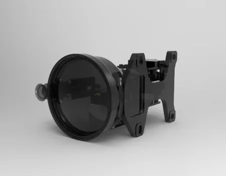
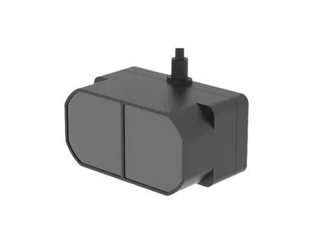
SentiAcu’s published SPL1K5 information, for example, lists a maximum range of 1,500 meters, a compact mass of approximately 11 grams with a stated tolerance, and different close- and long-range update-rate modes. Those figures belong to the specified model and its published conditions. They should not be generalized to every target or every product in the family.
Accuracy is closeness to a reference value, precision or repeatability is the spread of repeated measurements, and resolution is the smallest distinguishable change or sampling interval in range or angle.
These terms are often used interchangeably, but they answer different questions. A sensor can return nearly the same biased value every time, which is precise but inaccurate. Another sensor can average to the correct distance while individual measurements vary widely. The intended application determines whether bias, random noise, outliers, or latency is most important.
Accuracy should state the reference, distance interval, target, confidence or error statistic, temperature, and operating mode. A specification such as ±0.5 meter is more useful when accompanied by the range band and test conditions. SentiAcu’s published SPL1K5 page, for example, differentiates a stated ±0.5-meter accuracy at distances up to 80 meters and ±1.0 meter beyond 80 meters. That format is more informative than a single number applied to the full range.
Repeatability is commonly evaluated by holding a stable target and collecting many measurements. Useful statistics include mean, standard deviation, median, percentile error, outlier rate, and valid-return rate. The distribution may not be Gaussian, especially near the detection limit, on low-reflectivity surfaces, or when multiple objects are within the beam. Reporting only the average can hide dangerous outliers.
Range resolution can refer to the smallest reported increment, the ability to separate two returns, or the effective precision after signal processing. A display that reports millimeters does not prove millimeter accuracy. Angular resolution is the interval between measurement directions. Spatial spacing grows with distance. A scanner with 0.225-degree angular sampling has point spacing of approximately 0.39 meter at 100 meters using a small-angle approximation; beam size and motion can make the effective footprint larger.
For a mapping system, final accuracy includes much more than the range sensor. GNSS/INS error, timestamp alignment, lever arms, boresight, scan geometry, trajectory processing, control, and coordinate transformation all contribute. For a robot, sensor-to-robot calibration, motion distortion, algorithm delay, and map quality also contribute. Procurement should separate sensor-level accuracy from system-level outcome.
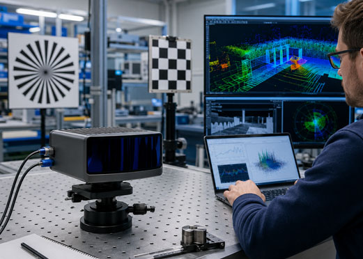
LiDAR spatial coverage is determined by field of view, angular or pixel sampling, scan pattern, beam size, frame or scan rate, and platform motion rather than by point rate alone.
Field of view defines the angular region the sensor observes. A wide field supports awareness but spreads available samples across a larger area. A narrow field concentrates measurements and may extend useful detail, but it covers less scene and requires accurate alignment. Horizontal and vertical fields should be stated separately for depth arrays and 3D scanners.
Angular resolution or pixel pitch determines the nominal direction spacing. The physical spacing between adjacent samples increases with distance. For small angles, spacing is approximately distance multiplied by angular interval in radians. This relationship helps buyers decide whether an obstacle, cable, branch, landing-zone feature, or machine edge will be represented by enough measurements.
Point rate is the number of range points generated per second. Scan rate is the number of completed scan cycles per second. Frame rate is the number of depth images per second. These quantities are related but not interchangeable. A scanner may have a high point rate but revisit a particular direction only once per scan. A depth array may update all pixels together at a lower numeric point rate but provide simultaneous scene coverage.
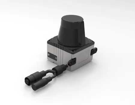
SentiAcu’s published LSM series information illustrates this distinction. The page lists a horizontal field of view of 270 degrees and point rates around 40,000 to 43,200 points per second for the referenced configurations, while angular resolution and scan frequency vary by model. The selection question is whether the resulting spacing and update behavior fit the moving platform and target, not which datasheet contains the largest standalone number.
Platform motion can distort a scan. Each point is acquired at a different time, so a moving sensor produces a geometrically warped scene unless motion is compensated. Mapping systems use trajectory data; mobile robots may deskew scans using inertial or odometry information. Buyers should ask whether timestamps are provided per point, per packet, per scan, or only when data reach the host.
Target reflectivity and geometry determine how much transmitted optical energy returns to the receiver and whether that return represents the intended surface.
Reflectivity values in datasheets are useful only when the measurement method and wavelength are understood. A surface can reflect differently at different wavelengths. Color in visible light is not a reliable predictor of near-infrared behavior. Surface roughness, moisture, coatings, incidence angle, contamination, and temperature can change the return.
Low-reflectivity targets reduce signal-to-noise ratio and may increase missing measurements, noise, or range bias near the limit. SentiAcu’s published LSM information specifies a 20-meter range on a 10% reflectivity condition for the referenced series, which is a more meaningful statement than a range with no reflectivity. Buyers should request similar condition-specific evidence for their actual surface.
Highly reflective surfaces can also cause problems. Retroreflectors may saturate a receiver. Glass can create multiple paths, transmit the beam, or reflect from the front and back surfaces. Shiny metal can produce angle-dependent returns. Water can reflect specularly or produce weak diffuse energy. Dust, fog, and rain create particles in front of the target and can generate near returns.
Multi-return systems may identify more than one reflecting surface along a beam, such as vegetation canopy and ground. The interpretation depends on pulse shape, receiver bandwidth, algorithms, and separation. Buyers should ask how returns are ordered, how many are reported, whether intensity is available, and how invalid or ambiguous cases are encoded.
LiDAR wavelength affects source and detector technology, atmospheric behavior, target response, eye-safety engineering, optical components, cost, and system packaging.
905 nanometers and approximately 1550 nanometers are common discussion points, but wavelength alone does not determine range or safety. The complete optical design, pulse energy, aperture, beam divergence, pulse repetition, scanning pattern, classification method, exposure geometry, and applicable standard must be considered. Buyers should request the product’s documented laser-safety classification rather than infer safety from wavelength.
Silicon detectors are widely used around 905 nanometers and can support compact, cost-effective designs. Longer wavelengths may use different sources and detectors and can support other design trade-offs. Component availability, detector noise, cooling, optical coatings, and manufacturing yield influence price. Atmospheric transmission and solar background also vary with wavelength and conditions.
Target reflectivity is wavelength-dependent. A surface that appears dark to the eye may return strongly at a near-infrared wavelength, while another coating may do the opposite. If the project involves a critical target material, representative testing at the intended wavelength is more reliable than using visual appearance or generic reflectivity tables.
Regulatory and safety requirements depend on jurisdiction, product class, use, access, scanning behavior, and system integration. The supplier should provide classification information and operating instructions, while the integrator remains responsible for the final product and use environment. This guide does not replace a formal laser-safety assessment.
LiDAR latency is the time between the physical measurement event and the availability of an interpreted result, while timestamp quality determines whether that result can be aligned with motion and other sensors.
Latency has several components: optical measurement, detector and signal processing, scan accumulation, internal filtering, packet creation, network transfer, driver buffering, host processing, and application logic. The average can appear acceptable while occasional spikes cause control errors. Real-time systems should evaluate worst-case or high-percentile latency, jitter, and measurement age.
Timestamp location matters. A timestamp created when a packet reaches the host is less useful than one linked to the measurement event, especially on a moving platform. Mapping and sensor fusion need a common time base across LiDAR, cameras, IMU, GNSS, encoders, and control computers. The interface document should describe clock source, synchronization method, timestamp resolution, drift, rollover, and behavior after a reset.
Filtering changes both noise and response time. Averaging several samples can improve repeatability on a static target but delay a moving edge. Outlier rejection can suppress dust or multipath, but it can also remove a real small obstacle. Buyers should request access to raw or minimally processed data during development and understand which filters are active in production.
Data quality should include validity flags, signal strength or confidence where available, temperature, sensor status, sequence counters, and error codes. A numeric range with no validity context can be more dangerous than a clear invalid result. Host software should never assume that every packet is current, complete, or physically plausible.
LiDAR sensor price is the purchase cost of the hardware, while total system cost includes integration, compute, navigation, calibration, software, validation, manufacturing, maintenance, and the operational cost of obtaining a reliable result.
Price varies because sensors solve different problems. A compact single-point module can use fewer optical channels and less processing than a dense three-dimensional scanner. A long-range design may require larger optics, higher-performance timing, different detector technology, tighter alignment, and more demanding environmental control. A wide field, high point rate, small packaging, and low power can conflict with each other and increase engineering cost.
Qualification and quality controls also affect price. Temperature testing, vibration, shock, sealing, electromagnetic compatibility, burn-in, calibration, traceability, and documentation add cost but may reduce project risk. A prototype unit and a production program have different economics. Non-recurring engineering, tooling, custom firmware, mechanical changes, certification support, and sample testing should be separated from unit price.
Software can be a major cost driver. A sensor with a stable interface, diagnostic tools, sample code, timestamp support, and clear documentation may reduce engineering time. A cheaper unit with undocumented behavior can consume months of development. For mapping, GNSS/INS and processing software may cost as much as or more than the scanner. For autonomous systems, validation and safety-related software can dominate.
When evaluating laser scanner proposals, compare the same scope: sensor, cables, mount, interface hardware, SDK, licenses, calibration, test report, warranty, lead time, minimum order, change control, and support. Ask for prototype and production pricing separately, and define what happens if a component or firmware version changes.
A useful LiDAR comparison connects each measurement architecture to the engineering capabilities and cost drivers that matter for a specific application.
| LiDAR type | Primary output | Main performance variables | Major cost drivers | Typical purchasing mistake |
|---|---|---|---|---|
| Single-point LiDAR | One distance along a defined line of sight | Range, reflectivity, accuracy, rate, beam divergence, alignment | Long-range optics, detector, timing, compact packaging, qualification | Assuming one long-range number applies to every target |
| 2D laser scanner | Profile across an angular plane | FoV, angular resolution, scan rate, point rate, range, motion distortion | Scanning mechanism, encoder, optics, processing, environmental reliability | Comparing point rate without scan geometry or latency |
| Pixel-array LiDAR | Depth image over a fixed field | Pixel count, FoV, frame rate, range, missing pixels, sunlight performance | Array detector, illumination, optics, calibration, thermal design | Assuming a depth image equals survey-grade 3D mapping |
| Dense 3D scanner | High-density point cloud | Point rate, channels, FoV, range, calibration, timing, trajectory integration | Optics, detectors, scanning architecture, compute, navigation, software | Buying by points per second and ignoring system accuracy |
| Integrated perception system | LiDAR plus camera, IMU, GNSS, radar, or processing | Fusion latency, coordinate alignment, confidence, failure handling | Multiple sensors, compute, software, integration, validation, support | Adding sensors without defining which decision each one improves |
There is no universal “best value” type. Value is the cost of achieving an accepted result with sufficient reliability. A single-point module can be the best value for height or range. A depth array can be the best value for local scene coverage. A calibrated mapping system can be the best value when the deliverable is a georeferenced point cloud.
Published product examples illustrate how LiDAR specifications differ by architecture and model, but they must be verified against the current datasheet and intended target conditions.
| Published example | Representative published information | Engineering interpretation |
|---|---|---|
| SPL1K5 single-point LiDAR | Maximum range 1,500 m; approximately 11 ±0.5 g; dimensions no more than about 25 × 26 × 13 mm; close-range rate up to 800 Hz and long-range mode around 60 Hz; stated accuracy bands vary around 80 m | Compact long-range line-of-sight ranging; confirm target, reflectivity, rate mode, interface, and current environmental specification |
| LSM series laser scanner | Published 20 m range on 10% reflectivity; 270° horizontal FoV; point rate around 40,000–43,200 points/s; model-dependent angular resolution and scan frequency; published accuracy around ±2 cm for referenced configurations | Useful for profile scanning, SLAM, industrial or robotic measurement; select by model-specific scan geometry and motion requirements |
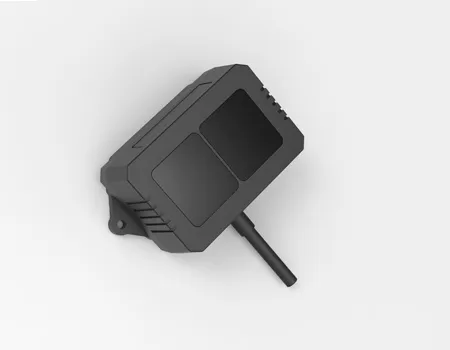
| PAL-S pixel-array LiDAR | Published 1,200-pixel dToF architecture; 9 m range; stated accuracy ±1% beyond 1 m; approximately 70 × 80 × 17 mm; 58.5° × 45.6° FoV; 17 Hz; 5 V supply; −20°C to +85°C published temperature range | Compact depth-image sensing for local 3D perception; evaluate pixel coverage, target size, sunlight, missing data, and required frame rate |
These values are provided as examples of specification structure, not as a substitute for a quotation, interface control document, or current technical datasheet. The buyer should confirm whether dimensions include connectors, whether rates are simultaneous with maximum range, what target was used, and what environmental or laser-safety requirements apply.
A LiDAR acceptance test is a repeatable, documented procedure that verifies range, accuracy, valid-return rate, coverage, latency, interfaces, environment, and failure behavior against the intended application.
Record sensor model, serial number, hardware revision, firmware, settings, filter mode, supply voltage, host software, interface, cables, target, reference instrument, weather, temperature, and mounting. A result without configuration control cannot be reproduced.
Use materials, sizes, angles, and backgrounds that represent the application. Include a favorable reference and one or more difficult surfaces. If reflectivity is specified, document how it is defined or measured at the relevant wavelength. Do not use only retroreflective tape unless the application uses it.
Use a reference method with uncertainty substantially smaller than the acceptance tolerance. Document calibration status, setup, alignment, and environmental corrections where relevant. The reference should measure the same physical point or geometry as the LiDAR as closely as practical.
Include minimum range, several intermediate ranges, required maximum operational range, and a margin where feasible. Collect enough samples to characterize bias, repeatability, outliers, and valid-return rate. Test both increasing and decreasing distance if hysteresis is possible.
For scanners and arrays, test center and edge of field, angular spacing, distortion, blind regions, and alignment. Rotate targets or sensor to representative incidence angles. For moving systems, repeat while the sensor or target moves.
Determine the time from physical event to output and the timestamp relationship. Record average, spread, and high-percentile delay. Verify behavior under network load, high point rate, logging, and processor stress.
Include strong ambient light, dark surfaces, reflective surfaces, multiple targets, dust or other relevant obscurants when safe and appropriate. Evaluate false returns, dropouts, recovery, and validity flags.
Disconnect communication, vary supply within allowed limits, interrupt power, send invalid commands, and simulate sensor obstruction. Confirm that the host detects the condition and does not continue using stale data.
When the application requires it, test temperature, vibration, humidity, shock, sealing, and electromagnetic conditions. Measure performance, not only survival. Record any warm-up or recalibration needs.
Acceptance thresholds should state statistic, sample size, confidence, allowable outlier rate, valid-return rate, target, distance, environment, and configuration. Do not change the criterion after seeing the data without a documented engineering decision.
A datasheet red flag is missing or ambiguous information that prevents a buyer from understanding whether a LiDAR specification applies to the intended target, mode, environment, or system.
Maximum range without target conditions. Ask for reflectivity, size, angle, atmosphere, background light, and valid-detection definition.
Accuracy without range interval or statistic. Ask whether it is maximum error, typical error, one standard deviation, or another metric.
Point rate presented as spatial resolution. Ask for field of view, angular pattern, scan or frame rate, and motion behavior.
Pixel resolution without missing-data information. Ask how many valid pixels remain on dark or distant targets and under sunlight.
Operating temperature without performance limits. Ask whether range and accuracy are maintained or only whether the unit remains functional.
No timestamp description. Ask where timestamps are generated, what clock is used, and how sensors synchronize.
No invalid-value protocol. Ask how out-of-range, low-confidence, saturated, obstructed, or internal-fault conditions are encoded.
Unclear dimensions and mass. Ask whether connectors, cables, mounts, enclosures, cooling, and external processors are included.
No revision control. Ask how hardware, firmware, calibration, and interface changes are communicated.
Claims copied across a product family. Confirm which values apply to the quoted model and configuration.
A LiDAR RFQ template converts the intended task into comparable technical, quality, integration, and commercial requirements for suppliers.
| RFQ field | What to state | Example of a measurable requirement |
|---|---|---|
| Application | Platform, environment, and decision supported | Downward height measurement for a multirotor during final 30 m of descent |
| Target | Material, reflectivity, size, angle, background | Dark soil and vegetation; specify representative samples for testing |
| Range | Minimum, normal, maximum operational, and margin | Valid measurement from 0.5 m to 30 m under stated conditions |
| Accuracy and quality | Bias, repeatability, outlier rate, valid-return rate | Define maximum error and required percentage of valid measurements |
| Coverage | Single point, FoV, angular sampling, pixel grid, scan pattern | Depth coverage of landing footprint with stated obstacle size |
| Rate and latency | Measurement, scan/frame, timestamp, maximum age | At least 50 valid updates/s with bounded end-to-end latency |
| Interface | Physical layer, protocol, units, clock, coordinate frame | Ethernet data plus defined time synchronization and status messages |
| Mechanical | Envelope, mass, mounting, field obstruction, connector | Maximum installed mass including mount and cable |
| Electrical | Voltage, peak power, inrush, grounding, EMC | Specified aircraft bus range with startup and transient behavior |
| Environment | Temperature, vibration, shock, sealing, sunlight, dust | Performance verification at required temperature endpoints |
| Safety and compliance | Laser classification, industry standards, documentation | Provide applicable classification report and integration instructions |
| Quality and lifecycle | Traceability, calibration, change control, repair, firmware | Serial-number configuration record and notification of changes |
| Commercial | Prototype, production quantity, lead time, MOQ, warranty | Separate NRE, sample price, volume tiers, tooling, and schedule |
SentiAcu supports specification comparison by relating product architecture and model-level data to target conditions, integration constraints, and a measurable acceptance plan.
A productive technical conversation should begin with the measurement task. State whether the system needs one range, a profile, a depth image, or a dense point cloud. Then define target, distance, accuracy, coverage, update rate, latency, size, weight, power, interface, environment, quantity, schedule, and testing. This information helps identify whether single-point LiDAR, an LSM scanner, a PAL depth sensor, or a multi-sensor architecture is appropriate.
For example, SentiAcu’s SPL products are oriented toward direct line-of-sight ranging, while the LSM category provides scanning measurement and the PAL category provides depth-array sensing. These categories differ in data output and integration burden. A buyer seeking a long-range number may need a single-point module; a buyer seeking obstacle geometry may need spatial coverage; a mapping buyer may need a complete scanner and navigation workflow beyond the sensor itself.
Where an application has unusual materials, low reflectivity, strong sunlight, vibration, temperature, or strict latency, representative testing should be included. SentiAcu can discuss samples, current technical documents, interface needs, and configuration-specific verification. The objective is to select a sensor that can be accepted with evidence, not to maximize every specification simultaneously.
These FAQs answer common procurement questions about interpreting LiDAR specifications and comparing products.
LiDAR range can vary from centimeters to many kilometers depending on architecture, wavelength, transmitted energy, optics, detector, target size and reflectivity, angle, atmosphere, sunlight, beam divergence, update mode, and detection criteria. The useful question is not the longest advertised range, but whether the sensor meets a required valid-return rate and accuracy on the actual target under representative conditions.
A good accuracy is one that is sufficient for the system-level decision after all errors are included. Industrial positioning may require millimeter- or centimeter-level performance, while long-range detection may tolerate larger absolute error. Define range interval, target, temperature, statistic, bias, repeatability, outlier rate, and system errors such as mounting, timing, navigation, and calibration before comparing values.
No. Angular resolution describes the spacing between measurement directions, while range accuracy describes how close a measured distance is to a reference. Angular spacing determines how densely a target is sampled and grows into larger physical spacing with distance. Beam divergence, scan pattern, motion, and calibration also affect effective spatial detail.
A higher-return target sends more optical energy back to the receiver, improving signal-to-noise ratio. Dark, wet, angled, small, or specular surfaces may return less energy or direct it away. Reflectivity also depends on wavelength. Maximum range should therefore be linked to a defined target and environment, and critical applications should test representative materials.
Price depends on measurement geometry, range, accuracy, wavelength, optics, detector, point or frame rate, packaging, environmental qualification, calibration, interface, production volume, and software. Total system cost may also include navigation, compute, storage, mounting, integration, testing, licensing, maintenance, and support. Request a scope-controlled quotation rather than comparing bare unit prices.
Provide the application, platform, target, reflectivity, minimum and maximum range, accuracy, valid-return requirement, field of view, resolution, rate, latency, interface, time synchronization, power, size, weight, environment, laser-safety or compliance needs, prototype and annual quantity, schedule, documentation, customization, and acceptance test. A representative target sample or recorded dataset can improve feasibility assessment.
A reliable LiDAR purchase is based on model-specific, condition-specific, system-relevant evidence rather than isolated maximum specifications.
Range must be connected to target reflectivity, size, angle, atmosphere, beam, and valid-detection criteria. Accuracy must be separated from repeatability and final system accuracy. Resolution must be identified as range, angular, pixel, or spatial resolution. Point rate must be interpreted together with field of view, scan or frame rate, timestamps, and platform motion. Price must include integration, software, validation, and lifecycle support.
The practical buying process is straightforward: define the decision the LiDAR supports, document representative targets and environment, create measurable acceptance criteria, request configuration-specific evidence, and test the sensor in the intended system. This approach makes supplier proposals comparable and reduces the risk of redesign after installation.
SentiAcu can support technical discussions across single-point, scanning, and pixel-array LiDAR. Share the target, distance, accuracy, coverage, rate, interface, platform constraints, environment, quantity, and acceptance method to receive a more relevant product and testing recommendation.
These independent sources provide authoritative background on measurement constants, LiDAR remote sensing, and geospatial accuracy standards.
NIST — Speed of light in vacuum: https://physics.nist.gov
NOAA Ocean Service — What is LiDAR?: https://oceanservice.noaa.gov/facts/lidar.html
ASPRS — Published geospatial standards and guidance: https://community.asprs.org/leadership-restricted/leadership-content/public-documents/standards