A 3D point cloud can look impressive and still be wrong. Dense colorized data, smooth surfaces, and millions of points do not prove that the measured geometry is accurate enough for inspection, navigation, volume estimation, digital reconstruction, or automation. The quality of a 3D laser scanner result depends on several linked factors: range error, angular error, sampling density, target reflectivity, incidence angle, platform motion, calibration, coordinate registration, environmental stability, and the algorithms used to filter and combine measurements.
That distinction is becoming more important for SentiAcu because current search performance is already showing interest around “laser point cloud scanning,” “point cloud laser scanning,” “3D point cloud laser scanner,” and related queries. Engineers searching those terms are usually not asking for a definition of LiDAR alone. They want to know whether a scanner can produce geometry that is useful after the data leave the sensor. This guide therefore focuses on point-cloud quality and measurement confidence rather than on visual appearance.
The article is written for B2B buyers, robotics teams, metrology engineers, surveying teams, automation integrators, and OEM developers comparing 3D sensing architectures. It also explains how to turn a vague requirement such as “high-accuracy 3D LiDAR” into measurable acceptance criteria.
3D laser scanner accuracy is the closeness of reported 3D coordinates to their true positions after range, angle, calibration, timing, and coordinate-transformation errors are considered.
A scanner does not measure x, y, and z independently in the way a coordinate table might suggest. Many LiDAR systems first estimate range and direction. Those polar measurements are then converted into Cartesian coordinates using the scanner’s angular calibration and coordinate frame. An error in range moves a point primarily along the line of sight. An angular error moves the point laterally, and the lateral effect grows with distance. Registration errors can then shift or rotate an entire scan relative to another scan or to an external reference frame.
This is why a single “±X mm accuracy” statement rarely tells the whole story. The value may describe range accuracy to a cooperative target under laboratory conditions, not final point-cloud accuracy on dark surfaces or at the edge of the field of view. It may be typical rather than guaranteed. It may exclude registration, platform pose, thermal drift, protective windows, or multi-scan alignment.
A robust specification should identify the measurand. Is the requirement absolute range, local surface flatness, relative point-to-point precision, object dimension, volumetric error, pose accuracy, or registered coordinate accuracy? Each can require a different test method.
A 3D laser scanner builds a point cloud by combining repeated distance measurements with known viewing directions and expressing the resulting samples in a common coordinate system.
Different architectures create this angular coverage in different ways. A mechanical scanner may rotate mirrors or the sensor assembly. A multi-channel sensor may emit or receive along multiple fixed directions. A flash or pixel-array LiDAR can capture multiple spatial samples with limited or no mechanical scanning. Regardless of architecture, each valid measurement must be associated with a direction, timing reference, and calibration model before it becomes a trustworthy 3D coordinate.
The result is a set of points that may also contain intensity, reflectivity, return number, confidence, timestamp, or classification information. If the scanner itself moves, as on a robot, drone, or vehicle, host pose must be estimated at the time of measurement. That is where IMU, GNSS, odometry, or SLAM becomes part of the point-cloud geometry.
For procurement, a 3d laser scanner should therefore be evaluated not only by how many points it produces, but by how those points are generated, timed, calibrated, and validated.
3D laser scanner point density describes how many spatial samples are collected, while accuracy describes how close those samples are to the true geometry.
A dense cloud can contain many biased points. If the scanner has a systematic angular calibration error, collecting more samples does not remove that bias. Likewise, a noisy sensor can produce a visually dense surface that is too rough for dimensional inspection. Density improves the chance of resolving small features, but it cannot replace calibration or traceability.
Point density should be matched to the application. A survey may express density in points or pulses per square meter. A short-range industrial scanner may instead be judged by angular sampling, pixel count, projected spacing at a working distance, or the number of samples across a feature. The correct metric depends on how the data are acquired.
USGS provides a useful example of why density and accuracy are treated separately. For its 3D Elevation Program, LiDAR quality levels are defined using both pulse spacing or density and vertical positional accuracy. QL2 collection requirements include at least 2 pulses per square meter and aggregate nominal pulse spacing no greater than 0.70 m, while the associated accuracy requirement is treated as a separate dimension. Those numbers are not a specification for industrial scanners; they illustrate the broader measurement principle that sampling density and positional accuracy answer different questions.
Angular resolution controls how closely neighboring measurement directions are spaced, so its effect on feature sampling becomes larger as target distance increases.
Suppose two adjacent rays are separated by a small angle θ. At short distance, their lateral separation is small. At longer distance, the gap grows approximately in proportion to range for small angles. A scanner may therefore resolve a narrow edge or cable at three meters but skip over it at thirty meters even if the range precision is unchanged.
Angular accuracy and angular resolution are different. Resolution describes the spacing between samples or the smallest commanded angular increment; angular accuracy describes how closely the real beam direction matches the reported direction. A system can have fine sampling but poor angular calibration. This distinction matters for 3D reconstruction because small angular biases create range-dependent lateral errors.
When evaluating a scanner, convert angular specifications into projected point spacing at the operational distance. Then compare that spacing with the smallest feature that must be detected or measured. This is more meaningful than comparing degree values without application context.
3D laser scanner point clouds become less complete or more uncertain when target reflectivity and incidence angle reduce the amount of returned optical energy.
Dark surfaces often produce weaker returns than bright diffuse targets. Highly oblique surfaces can direct less energy back toward the receiver. Glossy metal, polished coatings, wet surfaces, glass, and retroreflective materials can create additional edge cases. The result may be reduced range, increased noise, missing points, multipath effects, or inconsistent intensity.
This matters because missing data are not uniformly distributed. A scanner may map white walls perfectly while losing dark tires, black conveyor belts, or the edges of glossy machinery. A point cloud that looks complete in a demo room can therefore become fragmented in the real facility.
Acceptance testing should include representative materials at representative angles. The test report should record both positional error and valid-return rate. If the application uses intensity or reflectivity values for classification, verify their repeatability too; those values can change with distance, angle, gain settings, and environmental conditions.
3D laser scanner registration is the process of transforming separate scans into a common coordinate frame, and registration error can exceed the scanner’s internal range error.
Registration may be performed using targets, surveyed control points, feature matching, iterative closest point methods, SLAM, GNSS/INS, robot kinematics, or a combination. Each method introduces its own uncertainty. If two scans overlap poorly or contain repetitive geometry, the alignment algorithm can converge to the wrong solution. If the external pose system is biased, the entire cloud can be shifted even when individual ranges are excellent.
NIST work on 3D perception emphasizes the importance of performance metrics and standardized evaluation because downstream system behavior depends on more than sensor resolution. For B2B buyers, that means the acceptance test should distinguish intrinsic scanner performance from registration performance. If the scanner is being purchased for a mobile platform, ask how the supplier recommends synchronizing pose and range data.
A practical test is to measure known geometric artifacts from multiple scanner positions and compare the registered result with an independent reference. Check both local surface noise and global alignment. A cloud can be locally smooth but globally distorted.
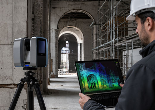
3D laser scanner calibration estimates systematic relationships between measured range, beam direction, timing, temperature, and the coordinate frame so repeatable errors can be corrected.
Factory calibration can include range offset, channel timing, detector response, angular mapping, optical distortion, and temperature compensation. A multi-channel or pixel-array sensor may require channel-to-channel calibration. A scanning mechanism may require encoder mapping or mirror calibration. The host platform adds another layer: the rigid transform between LiDAR, IMU, camera, robot body, or navigation frame.
Temperature and mechanical stability can be equally important. Optical mounts, housings, circuit boards, and scanning mechanisms expand or contract as temperature changes. Even when the internal electronics compensate range drift, a small change in angular alignment can create a larger lateral error at long distance. For a scanner installed on a moving platform, vibration can add short-term variation while shock can create a permanent shift in extrinsic calibration.
This is why an engineering team should avoid qualifying a 3D scanner only at room temperature on a rigid optical table. If the final product is installed outdoors, near an engine, inside a sealed enclosure, or on a vibrating robot, repeat geometry checks after thermal stabilization and representative mechanical exposure. The purpose is not to reproduce every lifetime condition in one test. It is to discover whether the dominant error source changes when the sensor leaves the laboratory.
Protective windows deserve special attention. A cover window can introduce refraction, ghost reflections, contamination sensitivity, and angle-dependent transmission. If the production design uses a window, qualification should use the same material, coating, thickness, tilt, spacing, and cleaning condition. Validating the bare sensor and adding the window later can invalidate part of the optical calibration.
Calibration does not remain valid automatically under every condition. Mechanical shock, bracket replacement, protective-window changes, temperature cycling, or repair can alter the system. Integration teams should therefore define which calibration is factory-controlled, which is performed during installation, and which should be checked periodically.
If the application is measurement-critical, keep a calibration history. Record device serial number, firmware, mounting configuration, calibration date, reference artifact, test environment, and results. Traceability is especially important when point clouds support quality decisions, dimensional inspection, or contractual acceptance.
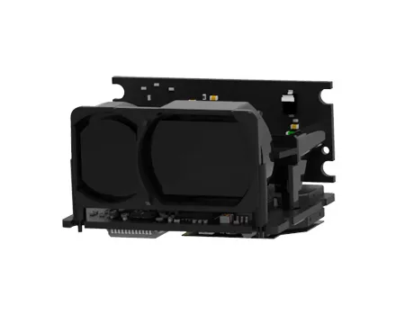
SentiAcu’s PAL-S illustrates how a compact 3D laser scanner specification combines spatial sampling, range, field of view, update rate, accuracy, power, and environmental limits.
The current SentiAcu PAL-S product page publishes a 1,200-pixel direct time-of-flight sensor, a 9 m range, accuracy of ±1% for distances above 1 m, a field of view of 58.5° × 45.6°, a 17 Hz frequency, 5 V DC power, and a stated operating temperature from -20°C to +85°C. The enclosure dimensions are published as 70 mm × 80 mm × 17 mm.
Those figures show why “3D scanner accuracy” should never be read alone. A buyer also needs to know the field of view over which the accuracy applies, the target used for the test, valid-return behavior, pixel geometry, temperature dependence, filtering, and whether accuracy is absolute or relative. The wide field of view and compact package may be valuable for spatial awareness, but the final suitability depends on the feature size and working distance of the application.
SentiAcu’s portfolio also includes laser scanner measurement products for scan-based ranging and Single Point LiDAR for dedicated distance channels. That creates an engineering choice between one range, a scan profile, and pixel-array 3D information rather than forcing every project into the same architecture.
A 3D laser scanner comparison should normalize target conditions, distance, field of view, accuracy definition, update mode, valid-return criteria, and environmental assumptions before ranking products.
Start by separating guaranteed specifications from typical values. Then identify the target reflectivity, incidence angle, ambient-light condition, and temperature. Confirm whether “range” means first detection, stable tracking, or rated accuracy. Ask whether the point rate includes invalid points and whether filtering reduces the effective update rate.
Next, examine geometric performance. Determine angular sampling, angular accuracy if available, minimum range, multi-return behavior, edge effects, and calibration stability. For multi-channel products, ask about channel alignment. For moving platforms, ask about timestamps and synchronization. For industrial integration, review vibration, ingress, EMC, connector, cable, and software requirements.
| Specification | What It Tells You | What It Does Not Prove | Recommended Verification |
|---|---|---|---|
| Range | Potential working distance under stated conditions | Performance on all reflectivities or weather conditions | Test real target materials at required distance |
| Range accuracy | Error along line of sight | Full 3D coordinate or registration accuracy | Measure known geometry across field of view |
| Pixel count / point rate | Sampling capacity | Point correctness or feature detectability | Calculate projected spacing at working distance |
| Field of view | Angular coverage | Uniform accuracy at the edges | Test center and boundary regions |
| Frame or scan rate | Temporal update frequency | End-to-end latency at the application | Timestamp measurements at host software |
| Operating temperature | Environmental design range | Constant accuracy across temperature | Repeat geometry tests across thermal range |
A 3D laser scanner acceptance test should measure the geometry that matters to the application using independent references, representative targets, multiple positions, and the final integration configuration.
For dimensional work, use artifacts with known planes, distances, spheres, steps, or other features that can be measured independently. For robotics, use repeated paths and known landmarks. For volume estimation, compare against an independently measured object or container. For surveying, use control points and a defined accuracy standard appropriate to the project.
Test across the field of view rather than only on-axis. Repeat at several distances and temperatures. Include dark, bright, oblique, and partially occluded surfaces. If the system moves, collect data at realistic speeds. If scans are registered, report both single-scan error and registered-cloud error. If software filters are used, freeze the configuration and document it.
For mobile or aerial applications, coordinate timing becomes part of the acceptance test. The lidar for surveying use case is a good reminder that point-cloud quality depends on both sensor data and the reference frame into which those data are placed. The exact workflow differs between a terrestrial scanner, robot, drone, and compact pixel-array module, but the principle is the same: validate the final measured product, not just the component output.
Define the required measurand before selecting the test artifact.
Use an independent reference that is meaningfully more accurate than the requirement.
Test center and edge of field of view.
Include representative reflectivity and incidence angles.
Separate raw-scan accuracy from registration accuracy.
Record firmware, calibration, filters, temperature, mounting, and software version.
These 3D laser scanner FAQs address common misunderstandings about point-cloud density, accuracy, registration, and real-world measurement performance.
No. More points improve sampling density but do not automatically reduce systematic range, angular, calibration, or registration error. Accuracy must be measured against an independent reference.
Point accuracy usually refers to the error of an individual measured coordinate under defined conditions. Point-cloud accuracy can include additional errors from registration, platform pose, timing, calibration, and coordinate transformation across many points or scans.
Because neighboring rays are separated by an angle. As distance increases, the lateral separation between those directions increases. The exact spacing depends on the angular pattern and range.
Yes. Dense data can contain systematic bias, noise, registration drift, or calibration error. Visual smoothness is not proof of traceable geometry.
There is no universal interval. It depends on the sensor architecture, mechanical stability, environment, shock exposure, temperature cycling, and measurement criticality. Use manufacturer guidance plus periodic verification against a known artifact.
Include working distance, required accuracy, smallest feature, field of view, frame or scan rate, target reflectivity, ambient conditions, platform motion, synchronization, interface, power, size, temperature, ingress needs, expected quantity, and acceptance method.
3D laser scanner accuracy is best understood as a system property created by the sensor, calibration, target, timing, platform pose, registration, and validation workflow together.
Point count and visual density are useful, but they are not substitutes for measurement confidence in a production system. A serious comparison separates range accuracy from angular accuracy, density from resolution, raw-scan performance from registered-cloud performance, and laboratory targets from real materials. It also defines what the final system is trying to measure.
For buyers evaluating SentiAcu or another 3D sensing architecture, the practical next step is to convert the application into a testable specification. State the working distance, smallest feature, required geometric error, reflectivity, field of view, update rate, platform motion, environmental limits, and coordinate frame. Then validate the proposed scanner with representative targets and an independent reference. That approach produces better procurement decisions and gives engineering teams a clear basis for acceptance.
The following references provide authoritative definitions and quality concepts for LiDAR point clouds and 3D perception systems.