A mobile robot does not need a laser scanner because “LiDAR is advanced.” It needs a scanner because the control stack requires spatial measurements that remain useful while the platform moves, turns, vibrates, approaches dark surfaces, passes glass, and shares compute resources with localization, planning, and safety functions. The difference between a successful robot and a frustrating prototype is often found in the details that are absent from a headline range specification: scan geometry, timestamp quality, low-reflectivity behavior, angular sampling, invalid-return handling, environmental stability, and the way the device is mounted into the final machine.
This engineering guide explains how to evaluate laser scanner measurement systems for SLAM, robot navigation, UGVs, AGVs, industrial automation, and other moving platforms. It does not treat the scanner as an isolated component. Instead, it connects optical performance to mapping quality, localization stability, controller latency, mechanical placement, and acceptance testing. That system-level view is especially important for B2B buyers because two scanners with similar nominal ranges can produce very different operational results.
A laser scanner measurement system is an active optical sensor that samples distance across multiple angles to create a spatial profile or point set of the surrounding environment.
A fixed single-beam range sensor answers one directional question: how far away is the target along this line of sight? A scanner adds angular sampling. In a 2D system, the sensor sweeps or electronically samples across a plane and reports a sequence of polar measurements. In a 3D system, the output covers additional elevation information so the host receives a spatial representation rather than a single profile.
The scanner may provide range, angle, intensity or reflectivity, timestamp, return quality, and diagnostic information. The host system transforms those measurements into a local coordinate frame and may further combine them with wheel odometry, IMU data, cameras, GNSS, or other sensors. SLAM software uses successive observations to estimate motion while building or updating a map. Obstacle detection and path planning use the same or related data to identify free space and hazards.
For procurement, “laser scanner” is therefore not one performance number. It is an information pipeline from transmitted light to a spatial measurement that must remain geometrically and temporally consistent enough for downstream algorithms.
A laser scanner supports SLAM by repeatedly measuring environmental geometry so the localization algorithm can match new observations against previous scans or an existing map.
In a 2D mobile robot, each scan may look like a ring or arc of range points around the platform. Walls, racks, pillars, machine edges, and other stable features become geometric constraints. As the vehicle moves, SLAM algorithms compare the observed geometry with earlier observations and estimate the robot’s change in position and orientation. The map and pose estimate are updated together.
Reliable SLAM therefore depends on more than maximum range. It needs enough spatial structure within the scanner’s field of view, sufficient angular sampling to preserve useful features, low timing uncertainty, and consistent measurement behavior. A scanner that intermittently loses dark surfaces can make a corridor look wider than it is. A timestamp offset can make stationary walls appear displaced while the robot turns. Poor mounting can allow vibration to introduce apparent geometry that does not exist in the environment.
NIST has highlighted the importance of performance metrics and standard test methods for 3D perception systems used in autonomous navigation, assembly, and inspection. That principle applies directly to scanner-based SLAM: a sensor should be evaluated by measurable performance in representative tasks rather than by a specification sheet alone.
Laser scanner performance on dark and low-reflectivity surfaces matters because weak optical returns increase measurement uncertainty and can create missing or unstable geometry in the robot’s map.
Warehouse floors, tires, black plastics, dark painted steel, rubber bumpers, conveyor belts, composite panels, and wet surfaces are common in real facilities. These materials may return much less light than a white calibration target. If the receiver has limited sensitivity or the signal-processing thresholds are not well tuned, the scanner may shorten its effective range, increase noise, or report invalid points.
Glass introduces a different problem. Depending on angle, coating, wavelength, contamination, and background geometry, the beam may partially transmit, reflect specularly, or generate multiple interpretations. No scanner should be assumed to “solve glass” in every configuration. Instead, the system designer should identify where transparent or mirror-like materials appear and decide whether scanner placement, additional sensing, protective barriers, or mapped constraints are required.
SentiAcu’s current laser scanner page publishes two useful engineering figures for its LSM series: up to 40,000 points per second and a stated 20 m range on low-reflectivity targets. The company also states that the series has been tested across 50 extreme conditions. These are manufacturer-published claims rather than universal LiDAR benchmarks, so buyers should confirm the exact model, target definition, test method, and environmental limits during quotation and validation.
The lesson is broader than one product. A scanner specification should state not just how far it sees, but what it sees at that distance.
Laser scanner scan rate determines how often the environment is sampled, while angular resolution determines how finely the scanner separates features across its field of view.
These parameters interact with robot speed. A slow platform in a structured warehouse may localize well with moderate scan frequency because the scene changes little between observations. A faster vehicle covers more distance between scans, increasing the burden on motion prediction and scan matching. Likewise, coarse angular spacing may be sufficient for large walls but may miss narrow poles, edges, or small openings at longer range.
Another useful metric is observability rather than raw density. SLAM needs stable geometric features that change predictably with motion. Long parallel corridors, repetitive racks, open yards, or feature-poor tunnels can reduce observability even when the scanner is returning thousands of valid points. In those environments, the integration team may need better odometry, IMU constraints, loop-closure logic, additional viewpoints, or complementary sensors. A scanner cannot create geometric uniqueness where the environment itself provides little of it.
Filtering must also be reviewed carefully. Temporal averaging can make a static wall look cleaner, but it can smear a moving obstacle or increase latency. Spatial filters can remove isolated noise, but aggressive settings may also remove narrow poles or thin edges that matter to navigation. When comparing two devices, ask for both raw and filtered behavior. A clean demonstration map may reflect software post-processing as much as optical performance.
Point rate is another related metric, but it should not be used by itself. Forty thousand points per second can be distributed in many ways depending on field of view, scan frequency, channel count, and filtering. The geometry seen by the algorithm depends on where those points fall in space and time. A dense cluster in one direction does not compensate for missing coverage in another direction that is critical to navigation.
A practical review should convert sensor specifications into expected point spacing at the operational distance. If angular spacing is θ, lateral separation grows approximately with distance. This means the same scanner that resolves a narrow feature at two meters may not resolve it at twenty meters. The correct specification must therefore be tied to the smallest feature that matters and the distance at which it must be detected.
A 2D laser scanner measures geometry primarily in one plane, while a 3D laser scanner adds vertical structure that can improve scene understanding at the cost of more data and processing complexity.
2D scanners remain effective because many indoor mobile robots operate on approximately planar floors and need reliable horizontal geometry for localization and obstacle detection. The data are compact, mature SLAM algorithms are widely available, and the mounting concept is easy to understand. When the environment contains overhanging objects, ramps, irregular terrain, pallets at different heights, vegetation, or complex outdoor structures, a 3D representation can provide information that a single scan plane cannot capture.
A 3d laser scanner or pixel-array architecture can also be useful when the application needs shape, volume, or richer scene features. However, the choice should be driven by the task. More dimensions increase bandwidth, memory, calibration needs, coordinate transformations, and algorithmic workload. The robotics team should confirm that the extra spatial information produces a measurable improvement in navigation or perception.
| Evaluation Area | 2D Laser Scanner | 3D Laser Scanner | Engineering Implication |
|---|---|---|---|
| Spatial coverage | One primary scan plane | Horizontal and vertical structure | Select based on obstacle geometry and terrain |
| Data volume | Lower | Higher | Affects CPU, memory, network, and logging |
| SLAM complexity | Often simpler for planar environments | Better suited to complex 3D environments | Algorithm maturity and compute budget matter |
| Mounting sensitivity | Scan-plane height is critical | Full extrinsic calibration is critical | Bracket stiffness and alignment affect geometry |
| Typical strengths | Indoor AGVs, AMRs, corridor navigation | Outdoor robotics, terrain, volumetric perception | Use the least complex sensor that meets the task |
Laser scanner timing affects moving robots because each range sample is captured at a specific moment while the platform may be translating or rotating.
If all points in a scan are treated as though they were captured simultaneously, motion can distort the observed geometry. The effect becomes more visible as scan duration, platform speed, or rotational rate increases. A wall that is straight in the world may appear curved or shifted in the sensor frame. Modern SLAM pipelines can compensate using IMU or odometry data, but compensation requires trustworthy timestamps and knowledge of the acquisition sequence.
End-to-end latency also matters. The sensor may acquire a scan quickly, but buffering, serial transport, driver scheduling, middleware, transformation, filtering, and SLAM processing can delay the final pose or obstacle update. For navigation, the relevant number is the age of the information when the planner uses it, not only the sensor’s internal scan frequency.
During integration testing, record sensor timestamps at the host and compare them with a shared clock. Verify whether timestamps represent the start, center, or end of the scan. If the system fuses IMU or wheel odometry, confirm the time base used by each source. A few milliseconds can matter on fast-moving platforms, especially during turns.
Laser scanner placement should maximize useful environmental geometry while minimizing occlusion, self-reflection, vibration, contamination, and blind zones created by the host platform.
A 2D scanner mounted too low may see floor irregularities as obstacles; mounted too high, it may pass above low hazards. A scanner recessed behind body panels can lose field of view. Nearby glossy surfaces can create reflections. Wheels, forks, suspension movement, cables, and cargo can intermittently enter the scan plane. These issues are easier to prevent in CAD than to solve later in software.
Mounting stiffness is equally important. SLAM assumes that the transform between the scanner and the robot body is known. If a flexible bracket vibrates or changes angle under load, the extrinsic transform becomes time-varying. The resulting map error can look like algorithm noise even though the root cause is mechanical.
Some platforms benefit from combining a scanner with a dedicated single point lidar channel. For example, a navigation scanner may map horizontal geometry while a separate downward or forward range sensor measures one critical clearance or height. Sensor specialization can simplify validation and provide an independent cross-check.
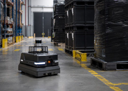
A laser scanner should be validated with a repeatable test matrix that covers distance, reflectivity, angle, motion, temperature, contamination, and the final software interface.
Start with static geometry so measurement error and repeatability can be isolated. Use several target materials: a high-reflectivity reference, a medium-reflectivity painted surface, and the darkest representative material expected in service. Measure at multiple angles because incidence can affect return energy. Record dropout percentage as well as average error; a sensor that is accurate only when it returns a value may still be unsuitable if too many points disappear.
Then add motion. Mount the device on the final or representative platform and drive repeated paths past known walls, poles, corners, ramps, and reflective surfaces. Compare mapping consistency between runs. Log raw scans, timestamps, odometry, IMU data, and the final SLAM pose. A test that stores only the final map can hide whether an error originated in the sensor, synchronization, motion compensation, or algorithm.
Environmental tests should include expected temperature, dust, vibration, sunlight exposure if applicable, and supply-voltage variation. Protective windows must also be included because their material, angle, coating, cleanliness, and distance from the sensor can alter optical behavior. Any configuration change after validation should trigger at least a focused regression test.
A laser scanner RFQ should specify the operational geometry and acceptance criteria rather than asking only for maximum range, accuracy, and price.
Good RFQs describe the host platform, operating speed, minimum feature size, required field of view, target materials, mounting height, temperature, ingress environment, power budget, interface, synchronization method, and software stack. They also define which performance metric is a requirement and which is only a preference. This helps the supplier avoid proposing an over-specified device that raises cost without improving the robot.
Ask for the target reflectivity associated with range claims, point rate at the selected scan frequency, angular increment, minimum range, scan duration, output format, timestamp behavior, invalid-point coding, configurable filters, warm-up time, environmental ratings, EMC evidence, and available manuals or SDKs. If the application is safety-related, separate navigation perception from certified safety functions unless the product and system have been developed and assessed for the relevant standard.
The RFQ should also request sample data or an evaluation unit when the environment is unusual. A short test with the real floor, target, or enclosure can answer questions that cannot be resolved from a PDF.
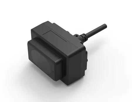
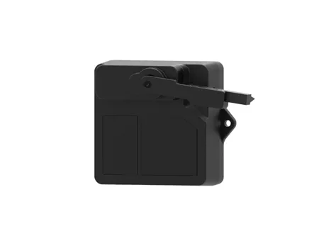
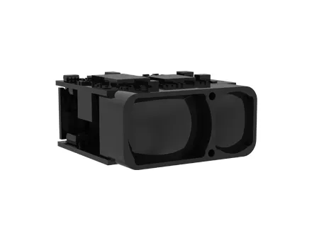
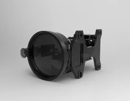
SentiAcu’s Laser Scanner Measurement portfolio is positioned for applications that need scan-based spatial data and can be combined with other sensing modes when one geometry channel is not enough.
SentiAcu separates its sensing portfolio into Single Point LiDAR, Laser Scanner Measurement, Pixel Array LiDAR, and Radio Frequency Sensor categories. For system architects, that separation is useful because it maps to different information needs. The LSM category addresses scan-based ranging, while SPL can provide a dedicated directional distance and PAL can provide richer 3D information.
The public LSM page emphasizes operation on challenging surfaces, 20 m low-reflectivity range, 40,000 points per second, and environmental testing across 50 conditions. Those published figures should be treated as starting points for a technical discussion. The exact model, configuration, target, filtering, temperature limits, and interface should be confirmed against the current datasheet and the customer’s validation plan.
For an engineering inquiry, send SentiAcu the platform type, indoor or outdoor environment, expected speed, scan plane or 3D coverage requirement, target materials, required range, minimum obstacle size, localization method, communication interface, supply voltage, and expected annual volume. The more clearly the robot task is defined, the easier it is to decide whether LSM, PAL, SPL, or a combination is appropriate.
No. Point rate is useful only when points are distributed in a geometry that supports localization and perception. Angular coverage, scan frequency, timing, range quality, and feature visibility matter just as much. Extra points can also increase bandwidth and compute load.
Yes. Many indoor robots operate successfully with 2D scanning when the environment is approximately planar and relevant obstacles intersect the scan plane. A 3D sensor becomes more valuable when vertical structure, irregular terrain, overhanging objects, or volumetric perception are important.
Black materials may reflect less optical energy back toward the receiver. At longer distance or oblique incidence, the return can fall below the detection threshold. Receiver sensitivity, wavelength, optics, signal processing, and environmental light all influence the result.
Glass is challenging because light can transmit through it or reflect specularly depending on angle and coating. No general claim should replace testing. If glass is common in the environment, validate representative panels and consider complementary sensing or mapped constraints.
Common causes include timestamp mismatch, motion distortion, poor odometry, incorrect extrinsic calibration, flexible mounting, wheel slip, insufficient geometric features, and loop-closure errors. Static range accuracy is only one part of map quality.
They should be evaluated together. The software must support the scanner’s data format, scan geometry, timing, and update rate, while the scanner must provide the environmental features the algorithm needs. Early hardware-software co-design reduces integration rework.
A laser scanner succeeds in robotics when its optical, geometric, timing, mechanical, and software behavior matches the complete navigation system.
For SLAM and autonomous movement, the useful question is not “Which scanner has the longest range?” It is “Which scanner produces stable, correctly timed geometry on the surfaces that matter, from the mounting position we can actually use, at the speed our platform will travel?” Range, angular resolution, scan frequency, point rate, low-reflectivity performance, latency, timestamping, and mounting stability must be considered together.
Use 2D scanning when a planar representation is enough. Move to 3D when vertical structure produces measurable value. Validate dark surfaces and glass rather than assuming laboratory targets represent the facility. Measure end-to-end latency at the application, not only sensor frequency. Most importantly, build an acceptance test around the robot’s task. That gives procurement, engineering, and the supplier a shared definition of success.
NEXT