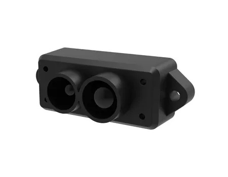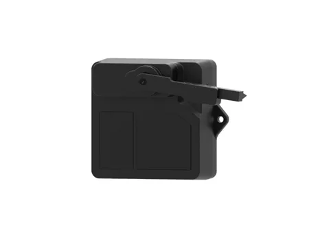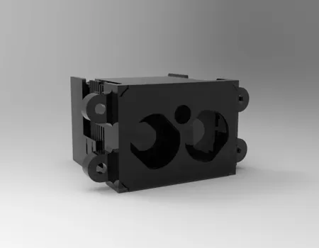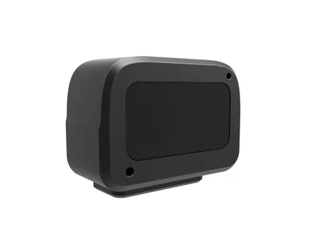
Engineers often encounter the terms “single point LiDAR,” “laser distance sensor,” “laser range sensor,” and “laser rangefinder” in the same specification search. The labels overlap, but the products behind them can be optimized for very different jobs. One device may be designed to return a stable distance to one target direction at high update rates, while another may prioritize human-readable ranging, a visible aiming interface, compact consumer packaging, or a broader scanning field. For an OEM integrator, the important question is therefore not which term sounds more advanced. It is what measurement architecture, optical design, signal processing, interface, environmental tolerance, and validation method are behind the name.
This guide explains the practical distinction from an engineering and procurement perspective. It focuses on how a single-beam time-of-flight system behaves, what changes when scanning is added, why dark or oblique targets reduce usable range, and which questions should appear in an RFQ. The goal is to help system designers choose a sensing approach that fits the mission rather than overpaying for capabilities that do not improve the actual measurement.
Single point LiDAR is a laser ranging architecture that measures distance along one optical line of sight and returns a range value rather than a spatial scan.
At its simplest, a single point LiDAR emits a laser pulse or modulated optical signal toward a target, detects the returned light, and estimates distance from the measured travel time or phase relationship. Because the sensor is not mechanically or electronically sweeping a scene to create a map, its processing budget can be concentrated on one direction. That makes the architecture attractive when an application needs direct range, height, clearance, proximity, or target distance rather than a full 2D or 3D representation.
The phrase “single point” describes the spatial sampling pattern, not necessarily a low-performance device. A single line of sight can still support long-distance ranging, fast updates, filtering, confidence outputs, gating, or multi-echo logic depending on the design. It may be integrated into a drone, vehicle, gimbal, industrial machine, robotics platform, or fixed monitoring system. The same architecture can be packaged for a short industrial distance or for much longer outdoor ranging, so the application requirements must be read together with the optical and electrical specifications.
For B2B buyers, this distinction matters because a single point device is usually easier to integrate when the system already knows where it needs to measure. If the platform only needs downward altitude, forward clearance, a fixed standoff distance, or one targeted range channel, building a dense point cloud may add cost, bandwidth, compute load, and calibration work without adding useful information.
Single point LiDAR commonly measures distance by converting the travel time of light into range through the relationship between propagation speed and round-trip delay.
The SI definition of the meter fixes the speed of light in vacuum at exactly 299,792,458 meters per second. For a direct time-of-flight measurement, the basic relationship is d = c × Δt / 2, where d is target distance, c is the speed of light, and Δt is the measured round-trip time. The division by two is essential because the transmitted light travels from the sensor to the target and then returns to the receiver.
This relationship makes clear why timing performance matters. A target one meter away produces a round-trip travel time of roughly 6.67 nanoseconds in vacuum. A change of one centimeter in distance corresponds to only about 66.7 picoseconds of round-trip time. Real products therefore do not achieve their stated accuracy simply by owning a fast clock. Detector jitter, optical pulse shape, signal-to-noise ratio, threshold algorithms, temperature drift, internal delays, calibration, atmospheric conditions, target reflectivity, and incidence angle all influence the final result.
Some compact distance sensors use phase-based or continuous-wave techniques rather than direct pulse timing. Others combine timing and signal-processing methods. This is one reason two products called “laser distance sensors” may behave very differently even if both report distance in millimeters or centimeters. For system integration, the measurement principle should be treated as one part of the specification, not as a substitute for real target testing.
Single point LiDAR and laser distance sensor are overlapping product categories, but “single point LiDAR” usually describes the sensing architecture while “laser distance sensor” is a broader functional label.
A laser distance sensor can refer to almost any device that uses optical energy to estimate range. It may be a small industrial module, a handheld instrument, a triangulation sensor for short displacement, a time-of-flight module, or a long-range ranging unit. Single point LiDAR is narrower: it normally implies active optical ranging along a defined line of sight, often with embedded electronics intended for machine or platform integration.
In practice, suppliers do not use terminology consistently. A procurement team should therefore avoid rejecting or selecting a product from the category name alone. Instead, compare whether the device provides raw or filtered distance, measurement confidence, reflectivity or signal-strength information, trigger modes, update-rate control, serial or fieldbus interfaces, environmental ratings, synchronization, and diagnostic status. These features often determine integration success more than the marketing label.
For engineers who are building a machine-facing range channel, the single point lidar product family is a more useful starting point than a generic search for handheld rangefinding equipment. The interface and control requirements are fundamentally different when the output must be consumed continuously by flight software, a robot controller, a perception computer, or an embedded safety function.
| Decision Factor | Single Point LiDAR | Generic Laser Distance Sensor | What the Buyer Should Verify |
|---|---|---|---|
| Spatial output | One primary line of sight | May be single-point, triangulation, or another architecture | Actual field of view and measurement geometry |
| Typical system role | Machine-integrated range, altitude, clearance, target distance | Broad category from industrial sensing to handheld measurement | Whether continuous OEM integration is supported |
| Update behavior | Often designed for repeated real-time ranging | Varies widely | Update rate under weak-return conditions |
| Interfaces | Commonly embedded serial, CAN, RS-485, or custom I/O depending on model | May be display-only or industrial I/O | Protocol, latency, timestamping, diagnostics |
| Target handling | May include filtering, gating, signal-strength logic | Highly product dependent | Dark, oblique, reflective, and partially obscured targets |
| Best selection method | Mission profile plus target testing | Application-specific validation | Do not select from maximum-range headline alone |
Single point LiDAR is usually the better fit when the system needs one trusted range channel and does not require a map of the surrounding scene.
A scanning LiDAR distributes measurements over many angles. That is valuable for localization, obstacle maps, shape reconstruction, corridor perception, or spatial modeling. It also introduces additional considerations: scan pattern, angular resolution, point rate, motion distortion, coordinate frames, point-cloud filtering, registration, and larger data bandwidth. A single point architecture avoids much of that complexity.
Consider a drone that only needs precise height above a landing surface. A downward range channel can directly feed altitude logic without requiring the flight computer to segment a point cloud. In a machine tool, a fixed optical range channel can monitor a known surface or standoff. In an industrial vehicle, one dedicated beam can serve a specific clearance check while a separate scanner handles navigation. The correct design is often a layered sensor architecture rather than an attempt to make one sensor do every perception job.
By contrast, if the system needs to know whether an obstacle is two degrees left or ten degrees right, or needs a contour of the environment, a laser scanner is the more appropriate starting point. The choice is therefore not “better technology” versus “worse technology”; it is a question of spatial information requirements.
A useful rule for early design reviews is to define the decision that the sensor output must support. If the controller only asks “how far away is the surface in this known direction?”, a single point channel can be efficient. If it asks “where are the relevant surfaces across an area?”, scanning is usually required.
Single point LiDAR range depends not only on transmitted power but also on how much optical energy returns from the target to the receiver.
Maximum-range figures are often measured on targets with defined reflectivity, size, orientation, and atmospheric conditions. A bright diffuse target facing the sensor is easier to detect than a dark material, a small object, a highly angled surface, or a target partially hidden by vegetation, dust, rain, or another object. Shiny surfaces can also be difficult because specular reflection may direct energy away from the receiver rather than back toward it.
This is why a buyer should always ask what target was used for the stated range. “Range: 1,000 m” is incomplete unless the supplier also explains target reflectivity, target size, visibility, probability of detection, false-alarm conditions, and whether the specification is typical or guaranteed. The same applies at short range: some optical systems have a minimum measurable distance or a near-field blind region caused by optical geometry, receiver recovery, or signal saturation.
For acceptance testing, use representative materials. If the final system must detect black rubber, wet asphalt, dark composite panels, vegetation, painted metal, or glass-adjacent surfaces, test those materials at the required angles and ranges. A white laboratory board is useful for repeatability, but it is not a substitute for the real mission target.
Single point LiDAR accuracy describes closeness to the true range, while precision and repeatability describe how tightly repeated measurements agree with one another.
These terms are frequently mixed in datasheets. A sensor can be very repeatable but biased, returning nearly the same value every time while remaining several centimeters away from a traceable reference. Conversely, a device can have a low average error but noisy individual samples. Resolution is different again: it is the smallest output increment or distinguishable change, not proof that the absolute measurement is accurate to that increment.
Procurement specifications should therefore separate four questions. What is the absolute range error across the working distance? What is the repeatability on a stable target? What is the output resolution? How does performance change with temperature, reflectivity, and incidence angle? If the application uses filtering, also ask whether the published accuracy applies to raw samples or filtered output.
System-level accuracy includes more than the sensor. Mechanical alignment, mounting tolerance, platform vibration, timestamp mismatch, coordinate transformation, and installation offset can all be larger than the internal ranging error. For a downward-looking airborne sensor, even a small angular mounting error creates lateral displacement that grows with height. For a machine-mounted unit, thermal movement of the bracket may become a systematic offset. Treat calibration as part of the system design.
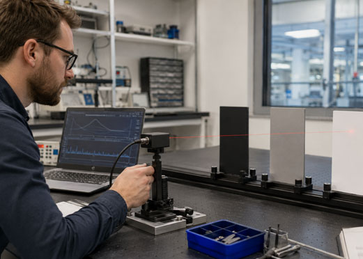
The required single point LiDAR update rate should be derived from platform speed, control-loop latency, stopping or response distance, and the dynamics of the measured surface.
A faster headline rate is not automatically better. High update frequency may reduce integration latency, but it can also reduce the time available to collect photons from weak targets. Some sensors trade measurement rate against maximum range or confidence. The buyer should ask whether the stated rate is maintained on low-reflectivity targets at the required distance and whether filtering adds additional delay.
A simple timing budget is more useful than an isolated number. Add sensor acquisition time, internal filtering, communication latency, driver buffering, operating-system delay, algorithm processing, and actuator or controller response. In a fast platform, a 20-millisecond end-to-end delay can be more important than a small difference in static range accuracy. Time synchronization is also important when range is fused with IMU, camera, GNSS, radar, or wheel-odometry data.
If the range channel will be used with other perception sensors, define how timestamps are generated and whether the device can accept an external trigger or synchronization signal. That requirement often appears late in projects, when it is expensive to redesign the interface.
Single point LiDAR selection for a mobile platform should balance range performance with size, weight, power, interface, environmental limits, and mounting geometry.
For airborne and mobile systems, range is only one part of the sensor budget. A long-range unit that exceeds the platform’s power allocation, cannot meet the temperature requirement, or produces data in an unsupported protocol may be unusable. Start with the mission: minimum and maximum height or standoff, expected closing speed, target materials, required update rate, accuracy tolerance, field of view, and environmental conditions.
Then define the platform constraints. Record available supply voltage, peak and average power, mass limit, envelope, connector orientation, vibration environment, EMI/EMC constraints, cable length, processor interface, and timing architecture. If the sensor is exposed, specify sealing, contamination management, window heating or cleaning strategy, and the possibility of sunlight entering the receiver field of view.
For a drone or unmanned platform that also needs scene perception, the dedicated range channel can complement broader lidar sensors for drones. One sensor may provide a direct, low-compute altitude or standoff measurement while another provides the wider spatial context. This separation can simplify fault detection because the system can compare independent measurements rather than relying on one perception pipeline for every function.
A single point LiDAR should be approved through target-based, environmental, timing, and interface tests that reproduce the intended installation rather than only a bench-top maximum-range demonstration.
A useful validation sequence begins with a traceable distance reference and several target materials. Test at multiple ranges, then repeat at different incidence angles. Record mean error, standard deviation, dropout rate, signal-strength behavior, warm-up drift, and the time required to recover after a very strong or very weak return. If the product has configurable filters, document every setting because a change in filtering can alter latency and apparent stability.
Next, test the installed configuration. Use the final cable length, power source, controller, bracket, protective window, and communication protocol. Apply vibration or platform movement representative of the real system. Check whether EMI from motors, radios, DC/DC converters, or high-current loads changes the data. Verify behavior during brownout, reboot, link interruption, and invalid-return conditions.
Finally, define what the system should do when the sensor is uncertain. A robust design needs an explicit invalid state rather than silently converting a weak return into a plausible distance. The controller should know the difference between “target at 30 m” and “no trustworthy measurement.” That distinction is essential for automation and safety-related logic.
Test at the minimum, nominal, and maximum required distance.
Include low-reflectivity and oblique targets, not only white calibration boards.
Measure end-to-end latency at the host application, not only sensor output rate.
Verify timestamp, checksum, invalid-data, and restart behavior.
Repeat tests across the expected temperature and supply-voltage range.
Document the final configuration so field units can be compared with the approved baseline.
SentiAcu positions its single point LiDAR portfolio as one part of a wider sensing architecture that also includes scanning LiDAR, pixel-array LiDAR, and radio-frequency sensors.
That portfolio approach is useful when a customer is deciding between a dedicated range channel and a spatial perception sensor. Instead of treating every requirement as a request for the highest-specification device, the engineering conversation can begin with the required output: one range, a 2D scan, a 3D field, or a fused perception solution. SentiAcu’s public product navigation separates Single Point LiDAR (SPL), Laser Scanner Measurement (LSM), Pixel Array LiDAR (PAL), and Radio Frequency Sensor (RFS), which mirrors these different information needs.
For an RFQ, provide the target distance range, expected target reflectivity, required accuracy and update rate, field-of-view constraints, environmental temperature, platform motion, available power, communication interface, and annual quantity. If the sensor will be fused with another device, include synchronization and coordinate-frame requirements. This information allows a supplier to recommend a configuration around the actual system rather than a generic maximum-range specification.
The most productive technical review also includes acceptance criteria. Ask what test target defines the range specification, what output indicates an invalid measurement, which parameters can be configured, whether the interface protocol is documented, and which environmental or EMC tests are relevant to the product. A clear acceptance plan reduces integration risk for both the buyer and the supplier.
These single point LiDAR FAQs address the practical questions that most often appear during sensor selection and integration.
They can use similar ranging physics, but the product intent may differ. A laser rangefinder may be designed for an operator and display a range, while a single point LiDAR module is often designed to deliver continuous machine-readable data to an embedded controller. Always compare interface, update behavior, target assumptions, diagnostics, and environmental requirements.
Not by itself from one fixed line of sight. A point cloud requires measurements across multiple spatial directions. A single point unit can be moved or mounted on a scanning mechanism, but once the system adds controlled angular sampling, pose tracking, and registration, the overall architecture becomes a scanning or mapping system rather than a simple fixed-beam range channel.
No. Maximum range is meaningful only with the target reflectivity, size, atmosphere, probability of detection, update rate, and accuracy. A sensor optimized for extreme range may be larger, more power-hungry, or less appropriate for short-range high-rate control. Select the range margin that the mission actually needs.
Dark materials often return less optical energy to the receiver. Lower return signal reduces signal-to-noise ratio and can increase dropout or uncertainty, especially at long distance or oblique angles. Test the actual target material whenever low reflectivity is expected.
There is no universal best interface. UART can be simple for compact embedded systems; CAN can be attractive in vehicles; RS-485 can support robust differential communication; Ethernet may suit higher-data products. The correct choice depends on cable length, bandwidth, EMI, existing network architecture, synchronization, and software support.
Do not select a device whose published maximum exactly equals the mission maximum. Build margin for weaker targets, contamination, temperature, atmospheric loss, installation angle, and unit variation. The margin should be justified by test data rather than a fixed percentage applied to every project.
The best single point LiDAR is the device that produces a trustworthy range under the real target, timing, environmental, and integration conditions of the system.
Single point LiDAR and laser distance sensor are not mutually exclusive categories. The first term usually describes a one-direction active ranging architecture; the second is a broader functional label that can include several optical principles and packaging styles. For B2B procurement, terminology should therefore lead to technical questions rather than replace them.
Start with the measurement decision, then define target properties, range, accuracy, update rate, latency, interface, environmental limits, and failure behavior. Compare those requirements with scanning needs before adding the cost and complexity of a point-cloud sensor. Finally, validate the selected device with representative materials and the final installation. That process produces a more defensible sensor choice and gives the supplier a much clearer basis for configuration and quotation.
The following references provide authoritative background on optical ranging, SI distance measurement, and high-accuracy LiDAR principles.